
Memory mapped spin lock controller

a memory-mapped, spin lock controller technology, applied in the field of multiprocessing system, can solve problems such as the possibility of conflict, the invalidation of all other public copies, and the observation of certain inefficiency

Inactive Publication Date: 2006-06-29
HEWLETT PACKARD DEV CO LP
View PDF0 Cites 16 Cited by
  • Summary
  • Abstract
  • Description
  • Claims
  • Application Information

AI Technical Summary

Benefits of technology

The invention relates to a method for managing a spin lock between two processors in a computer system with a centralized spin lock controller arrangement. The method includes invalidating a first private copy of a line of memory that is held by the first processor and providing a second private copy of the line to the second processor before the first processor releases the spin lock. This prevents the second processor from requesting a private copy of the line again while the spin lock is still held by the first processor. The invention also includes a computer-readable code for providing a first private copy of the line to the first processor and permitting the first processor to write the private copy of the line in a cache of the first processor without signaling the centralized spin lock controller arrangement that the first processor is going to write to the private copy of the line if no other processor of the plurality of processors contend for the spin lock. The technical effects of the invention include improved efficiency and reliability in managing spin locks between processors in a computer system.

Problems solved by technology

When multiple CPUs attempt to write (or update) to the same block of memory, a potential for conflict arises.
However, if the CPUs are simply allowed to compete anew each time a spin lock is released, certain inefficiency is observed.
If the CPU needs to modify a public copy that it currently holds, it needs to cause all other public copies to be invalidated.
In this case, the copies of the memory line at the CPUs that did not successfully obtain the spin lock in the next turn would need to be invalidated.
In doing so, bus traffic is needlessly wasted.
Additionally, the time required to furnish copies of the line of memory to the CPUs that will not be given control of the spin lock, as well as the time required to invalidate those copies once the spin lock is furnished to the winning CPU, would detrimentally affect performance.
In this case, it is highly desirable that there be no traffic on the system bus since the cumulative effect of multiple CPUs continually querying for their turn would detrimentally affect the system bus bandwidth.
While the prior art approach solves the fairness problem and substantially minimizes unnecessary bus traffic, the implementation of spin lock control in software introduces latency into a critical performance path.
This is because, generally speaking, a software-oriented implementation tends to be less efficient than one implemented in hardware.

Method used


Image

  • Memory mapped spin lock controller
  • Memory mapped spin lock controller
  • Memory mapped spin lock controller

Examples


Embodiment Construction

[0023] The present invention will now be described in detail with reference to a few preferred embodiments thereof as illustrated in the accompanying drawings. In the following description, numerous specific details are set forth in order to provide a thorough understanding of the present invention. It will be apparent, however, to one skilled in the art, that the present invention may be practiced without some or all of these specific details. In other instances, well known process steps and / or structures have not been described in detail in order to not unnecessarily obscure the present invention.

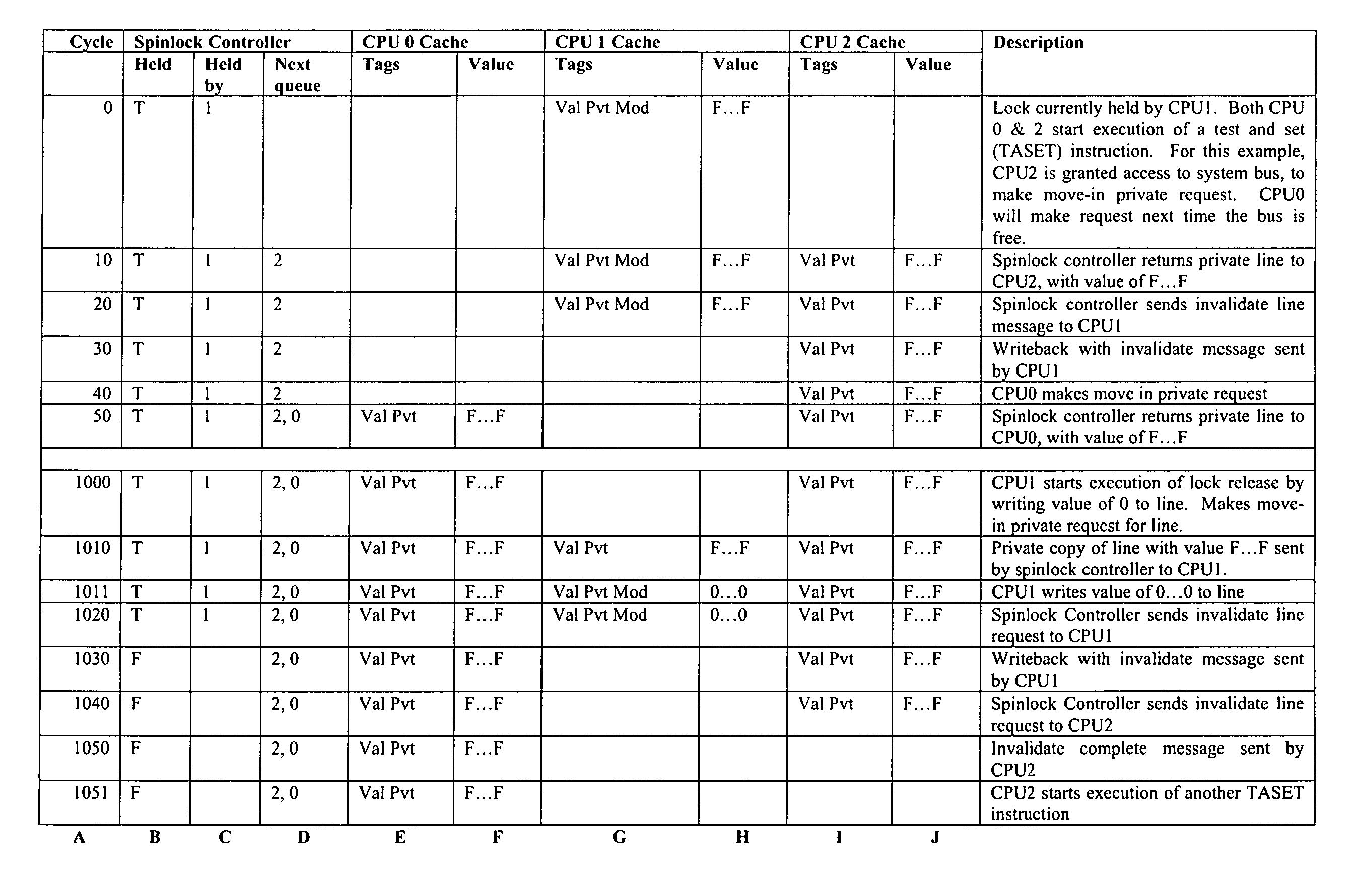
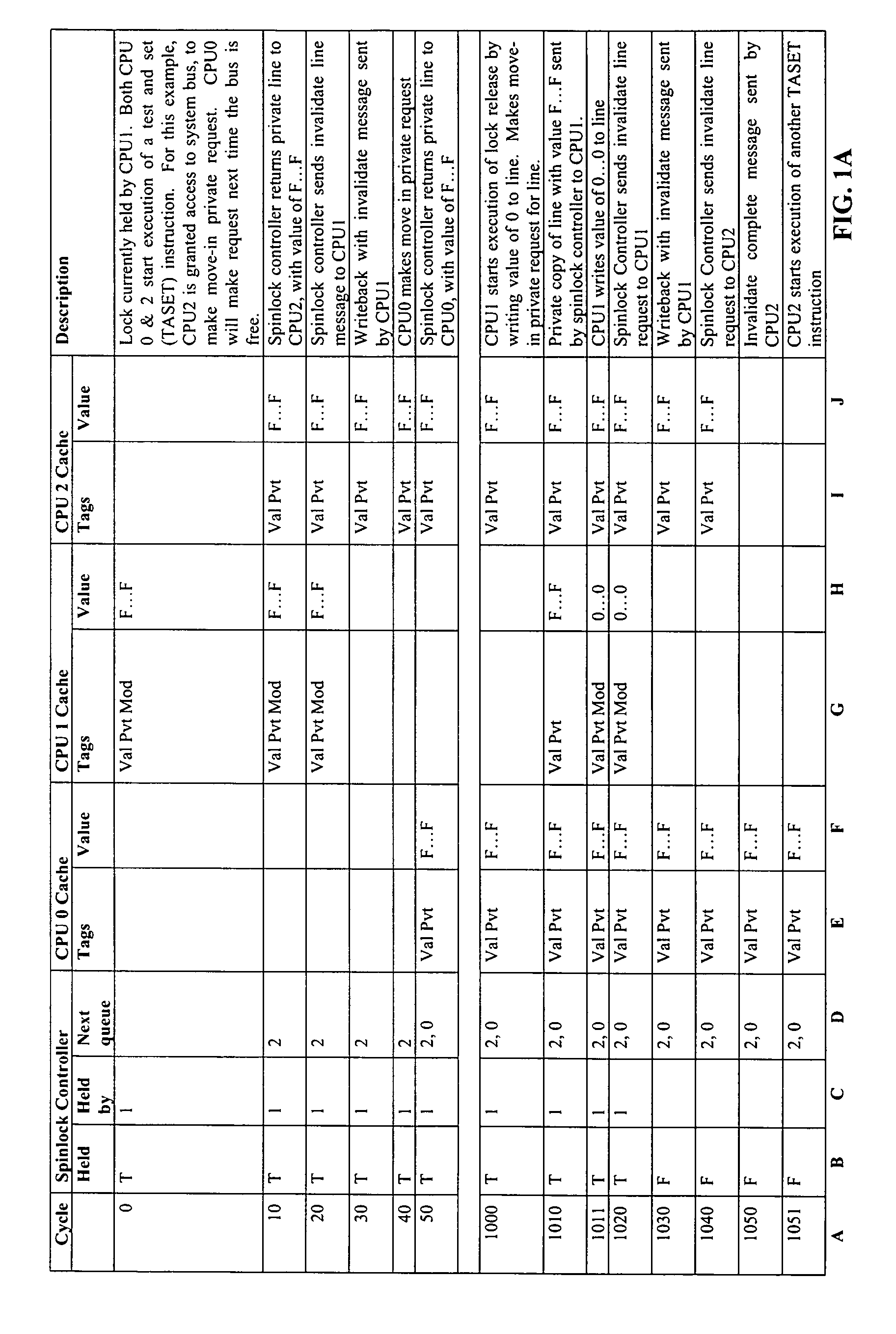
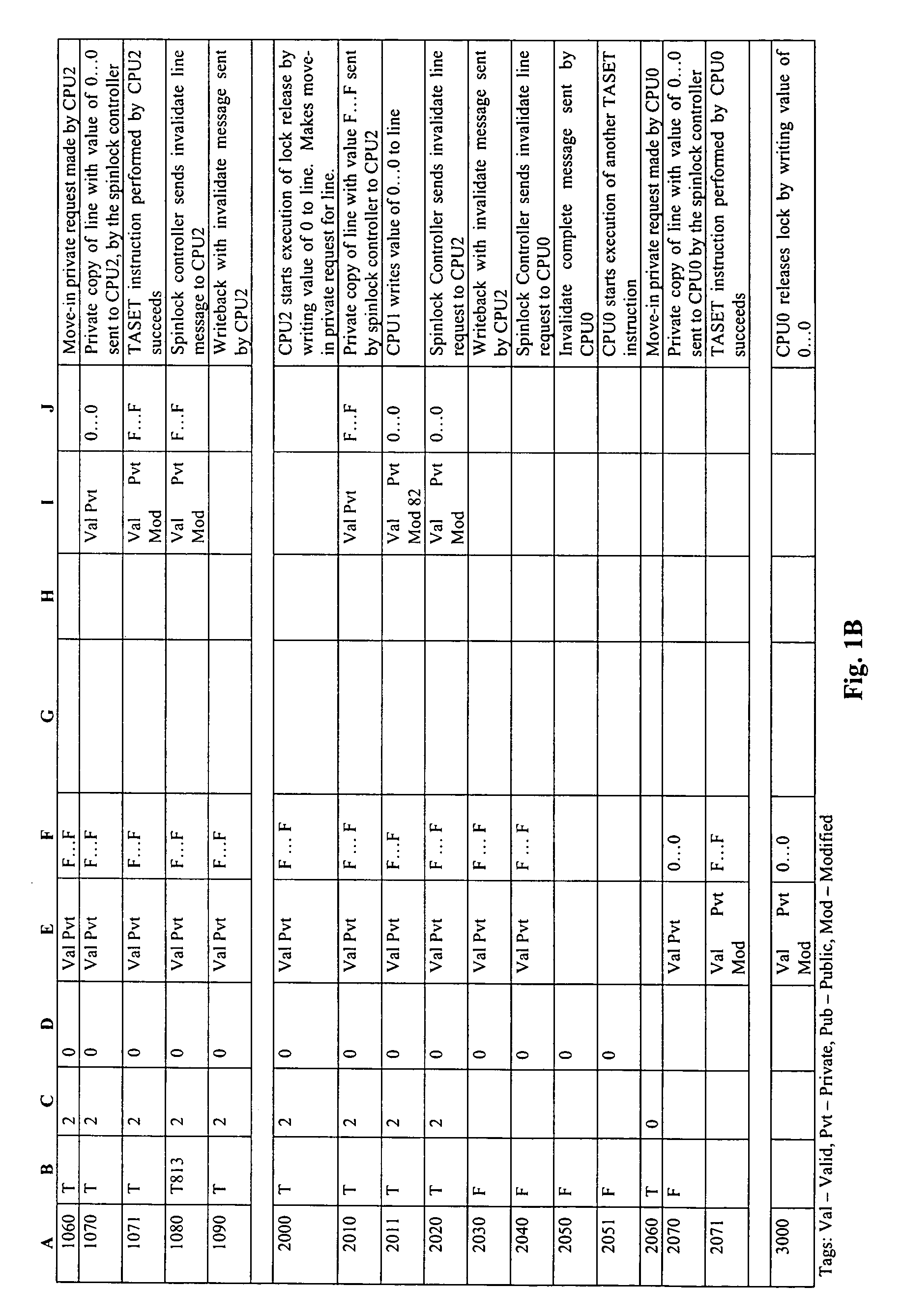
[0024] The following figures and discussions are directed toward embodiments of the memory mapped spin lock controller. In the following example, four CPUs (CPU0-CPU3) wish to have control of the lock at various times. To minimize the length of the example, the sequence will start with the lock already held by CPU1. For this example, it is assumed that a CPU employs the test-and-set inst...


PUM


Abstract

A method, in a computer system having a centralized spin lock controller arrangement, for managing a spin lock between a first processor and a second processor. The first processor holds the spin lock, the second processor contends for the spin lock, and the spin lock is implemented using a line of memory. The method includes invalidating a first private copy of the line that is held by the first processor. The method further includes providing a second private copy of the line to the second processor even before the first processor releases the spin lock, thereby preventing the second processor from requesting for a private copy of the line again while the spin lock is still held by the first processor.

Description

BACKGROUND OF THE INVENTION [0001] In a multi-processing system, there will be times when multiple processes wish to atomically access a given block of memory. As an example, multiple processes may wish to perform an operation commonly known as a read-modify-write sequence. During a read-modify-write sequence, a value is read from a given block of memory by a process, manipulated in a process specific manner, and then either the original value is left unmodified or the result of the manipulation is written over top of the original value. [0002] A block of memory, in the sequential memory model, may be viewed as a contiguous chunk of memory. Atomic access means that once the reading or writing is begun by a CPU, such reading or writing cannot be interrupted or interfered with by any other memory operation to the same block of memory, such as from any other CPU or I / O device, on the system. When multiple CPUs attempt to write (or update) to the same block of memory, a potential for co...

Claims


Application Information

Patent Timeline
Patent Type & Authority Applications(United States)
IPC IPC(8): G06F11/00
CPCG06F9/526G06F9/3004G06F9/30087
Inventor HUEMILLER, LOUIS D. JR.
Owner HEWLETT PACKARD DEV CO LP
Learn More