
T-nut

a technology of t-nuts and bolts, which is applied in the direction of threaded fasteners, fastening means, mechanical equipment, etc., can solve the problems of time-consuming and complicated removal of oil or paint, and the bolt cannot be smoothly mounted in the female screw portion of the t-nu

Inactive Publication Date: 2006-06-29
NAGAYAMA ELECTRONICS IND
View PDF26 Cites 2 Cited by
  • Summary
  • Abstract
  • Description
  • Claims
  • Application Information

AI Technical Summary

Benefits of technology

[0013] The same inventor as the present invention has developed a T-nut having a bottom-sealing member (not shown), which completely seals the opening portions 11A,31A as described above, in order to prevent the oil or paint from entering the shank 12, 32 therefrom.
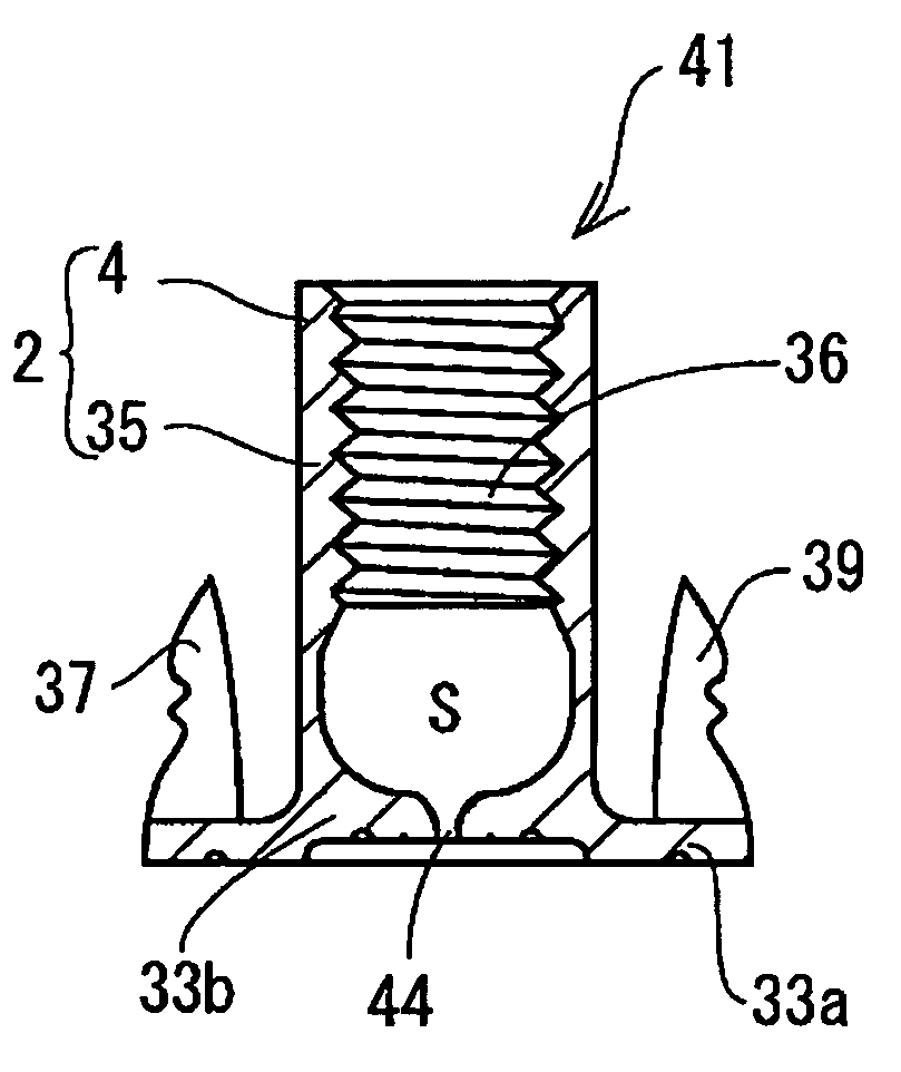
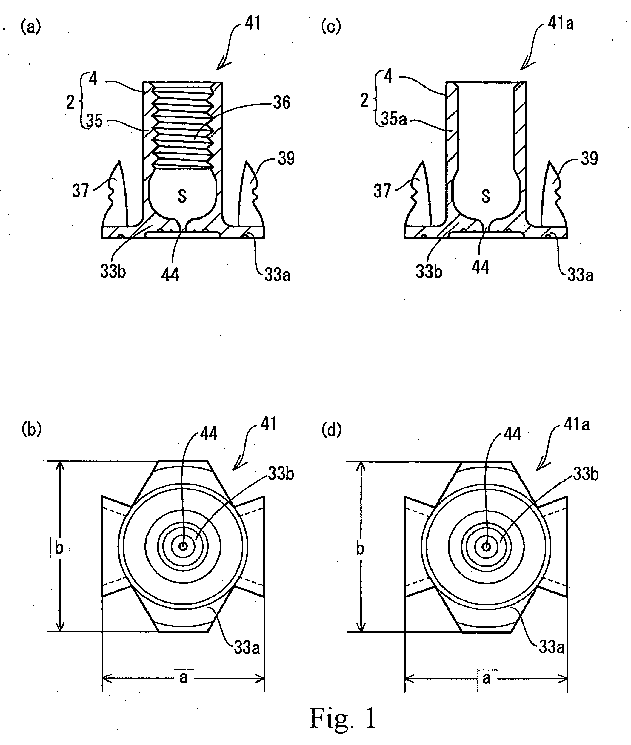
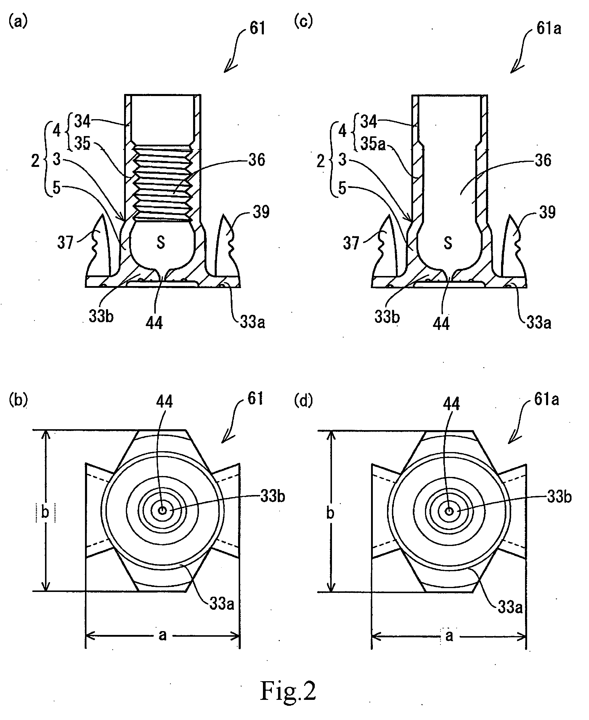
[0039] The T-nut of the present invention has the internal flange portion almost closing the first end of the shank, so as to prevent paint and oil from entering thereinside, but since a hole is formed at the center of the internal flange portion such that a small amount of viscous oil can be entered therethrough to lubricate the inside surface of the shank. When a volt is screwed with the shank, it can be smoothly screwed by the lubricant. Further, because the T-nut of the present invention has the hole as mentioned here, air inside the shank can be released therethrough at the time when the volt is screwed with the shank, promoting the easiness in engaging the volt with the shank. These effects of the present invention can be obtained not only in the T-nut having a female screw portion inside the shank, but in the T-nut without the female screw portion.
[0041] Also, according to the present invention, the T-nut has a to-be-caulked portion formed in the shank, which provides an effect that the T-nut is firmly fixed in a fixing object by a caulking process.
[0042] Also, according to the present invention, the T-nut has a stepped portion formed in the shank, which provides an effect that the T-nut is firmly fixed to the fixing object. Further, an enlarged tubular bottom portion is formed over the portion from the stepped portion to the external flange portion, so that the enlarged tubular bottom portion is pressed toward the through hole of the fixing object when the T-nut is driven into the fixing object, further securing the fixation of the T-nut to the fixing object.
[0043] Also, in an embodiment that the T-nut according to the present invention has a to-be-caulked portion with an inner diameter greater than that of the female screw portion and an outer diameter greater than that of the female screw portion, it is necessary to make the diameter of the bottom hole of a fixing object larger than at least the outer diameter of the to-be-caulked portion. In a condition where the T-nut is driven into the fixing object, a gap can be generated between the female screw portion and the inner surface of the bottom hole. However, the caulking of the to-be-caulked portion can ensure the fixation of the T-nut to the fixing object.

Problems solved by technology

However, it is a complicated and time-consuming matter to remove the oil or paint entered into the inside of the shank 12, 32 of the T-nuts 11, 31.
Together with the missing of the above described lubricant, there has been concerned that the bolt can not be smoothly mounted in the female screw portion of the T-nut.

Method used


Image

  • T-nut
  • T-nut
  • T-nut

Examples


Embodiment Construction

[0103] Hereinafter, the present invention is described based on the embodiment with reference to the drawings.

[0104] As shown in FIGS. 1(a)(b) and FIG. 4(a), a T-nut 41 according to one embodiment of the present invention comprises a tubular shank 2, an external flange portion 33a that extends outwardly from a first end of this shank, an internal flange portion 33b that extends inwardly, opposite to the direction of the external flange portion 33a of the above tubular shank 2, and two pairs of claws, 37 and 38, 39 and 40 that extend to a direction from the first end to a second end, i.e. vertically or substantially vertically to the external flange portion 33a, on a periphery part of the external flange portion 33a, which are integrally formed by pressing from a metal plate. The T-nut of the present invention further comprises a female screw portion 35 where a female screw 36 is formed at least on one part of the shank 2, and a small through hole 44 formed near the center of the in...


PUM


Abstract

There is provided a T-nut having a tubular shank 2, an external flange portion 33a extending outwardly from a first end of the shank 2, and an internal flange portion 33b extending inwardly opposite to the external flange portion 33a of the tubular shank 2, all of which are integrally formed from a metal plate by pressing. A hole 44 is formed at the vicinity of the center part of the internal flange portion 33b. This hole 44 allows the oil to enter the inside of the tubular shank to the extent that the oil is served as a lubricant.

Description

FIELD OF THE INVENTION [0001] The present invention relates to a T-nut having an external flange extending outwardly and an internal flange extending inwardly from one end of a hollow shank. BACKGROUND OF THE INVENTION [0002] There has been known T-nuts, as disclosed, for example, in Japanese Patent Laid-Open Publications Nos. H04-341606 or H06-323315. These T-nuts have a shank having a to-be-caulked portion which is made thin in the thickness. [0003] A T-nut 11 disclosed in the above Japanese Patent Laid-Open Publication No. H04-341606 has a shape as shown in FIG. 23(a)(b), comprising a shank 12 and a flange 13 extending outwardly from a first end of the shank 12, which can be integrally formed, for example, by processing an iron-based metal plate. [0004] The shank 12 has a hollow tubular shape with an even outer diameter. The shank 12 includes a to-be-caulked portion 14 at a second end of the shank, which is the other side of the first end, and has a female screw 15a formed in the...

Claims


Application Information

Patent Timeline
IPC IPC(8): F16B37/04
CPCF16B37/048
Inventor NAGAYAMA, YUTAKA
Owner NAGAYAMA ELECTRONICS IND
Learn More