
Image forming apparatus

Active Publication Date: 2006-06-29
RICOH KK
View PDF10 Cites 4 Cited by
  • Summary
  • Abstract
  • Description
  • Claims
  • Application Information

AI Technical Summary

Benefits of technology

[0009] It is an object of the present invention to provide an image forming apparatus capable of executing stable charge control, promoting easy, efficiently assembly and maintenance and saving space.

Problems solved by technology

While the charger charges the surface of the image carrier by applying a current fed from a high-tension power supply, the charge to be deposited on the above surface is apt to become unstable due to, e.g., the wear or similar deterioration of the image carrier ascribable to aging and due to filming of impurities.
However, a problem with the openable support plate scheme stated above is that when the support plate is opened, the contact portion of the image carrier and that of a member mounted on the support plate to form a current return path are apt to become unstable due to repeated opening and closing of the support plate.
Moreover, impurities deposited on the above contact portions or deterioration of the contact portions make current sensing more unstable, so that even the feedback control fails to stabilize the charge and maintain high image quality.

Method used


Image

  • Image forming apparatus
  • Image forming apparatus
  • Image forming apparatus

Examples


Embodiment Construction

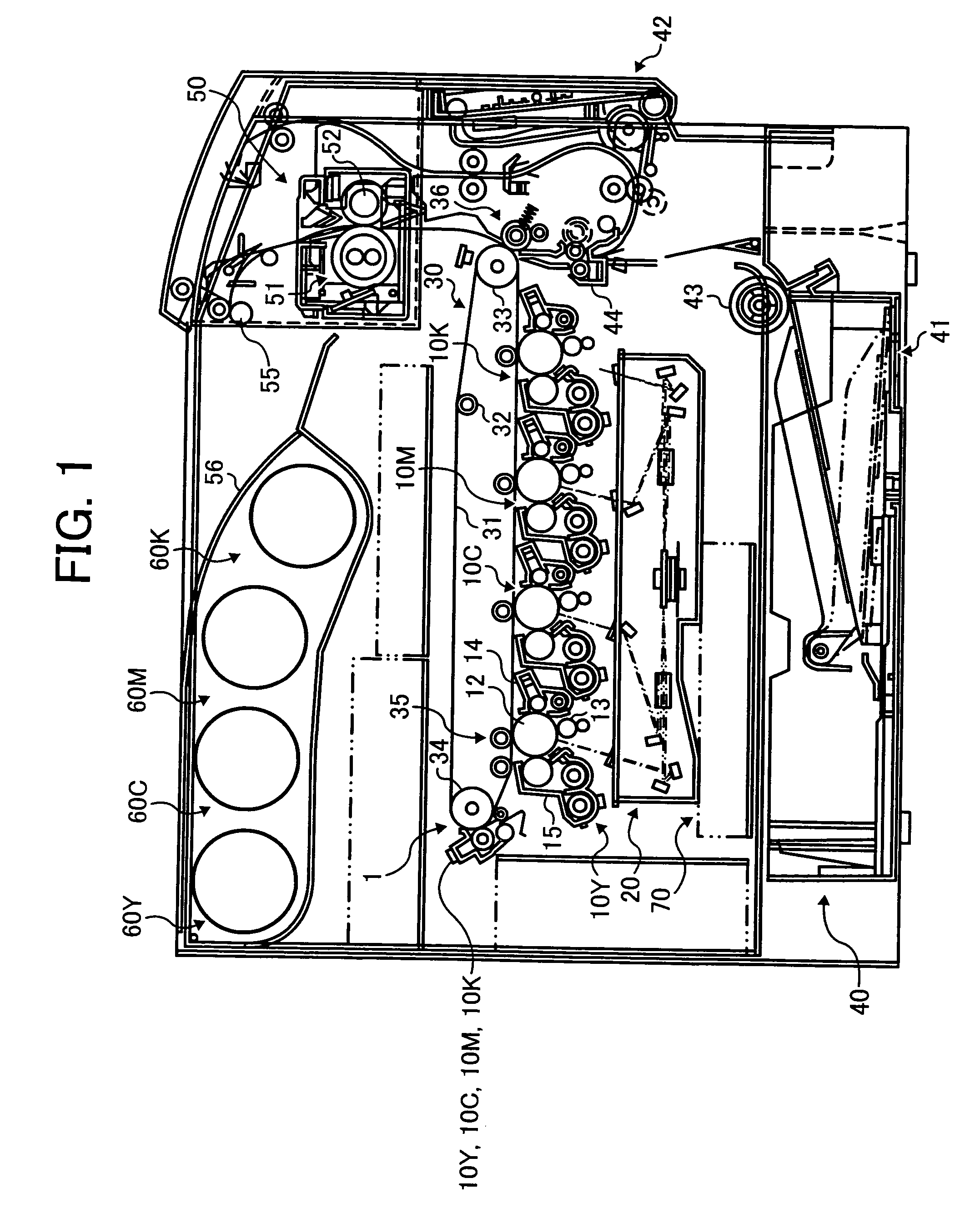
[0029] Referring to FIG. 1 of the drawings, an image forming apparatus embodying the present invention is shown and implemented as a full-color laser printer byway of example. FIG. 1 shows the full-color laser printer (simply printer hereinafter) as seen from the left side of the printer body. As shown, the printer includes a tandem image forming section 1 in which a yellow, a cyan, a magenta and a black image forming means 10Y, 10C, 10M and 10K, respectively, are arranged side by side from the left to the right in FIG. 1. It is to be noted that the suffices Y, C, M and K stand for yellow, cyan, magenta and black, respectively, and apply to various members to be described hereinafter also.

[0030] The toner image forming means 10Y, 10C, 10M and 10K include photoconductive drums 12Y, 12C, 12M and 12K, respectively, which are a specific form of an image carrier each. A charger, a developing device, a drum cleaner and so forth are arranged around each of the photoconductive drums (simpl...


PUM


Abstract

An image forming apparatus of the present invention includes a pair of support plates supporting the rotary shaft of a photoconductive drum at axially opposite ends of the drum. One of the support plates is openable away from the body of the apparatus and loaded with a contact forming member including a current feed path for feeding a current from a high-tension power supply for charging to a charge roller, a wiring forming a current return path that allows a current to flow from the photoconductive drum to the ground of the power supply, and a plurality of contacts where the wiring and drum contact each other. A current flowing through the current return path is sensed to execute feedback control to the output of the high-tension power supply.

Description

BACKGROUND OF THE INVENTION [0001] 1. Field of the Invention [0002] The present invention relates to a copier, facsimile apparatus or similar image forming apparatus of the type forming an image by an electrophotographic process. [0003] 2. Description of the Prior Art [0004] It is a common practice with an image forming apparatus of the type described to uniformly charge the surface of an image carrier with a charger, electrostatically form a latent image on the charged surface of the image carrier, develop the latent image with toner stored in a developing unit to thereby form a corresponding toner image, and transfer the toner image to a sheet or recording medium. While the charger charges the surface of the image carrier by applying a current fed from a high-tension power supply, the charge to be deposited on the above surface is apt to become unstable due to, e.g., the wear or similar deterioration of the image carrier ascribable to aging and due to filming of impurities. [0005]...

Claims


Application Information

Patent Timeline
IPC IPC(8): G03G15/00
CPCG03G15/0208G03G15/80G03G2215/0132
Inventor WASHIO, TAKESHIYOKONO, MASAHARUKUMA, KAZUOSA
Owner RICOH KK
Learn More