
Liquid container and recording apparatus

a technology of liquid containers and recording equipment, applied in the field of liquid containers, can solve the problems of affecting the function of informing users of the amount of remaining ink, affecting the brightness of the user's eyes, etc., and achieve the effect of reducing the variations in the brightness of the light-emitting uni

Active Publication Date: 2006-06-29
CANON KK
View PDF11 Cites 4 Cited by
  • Summary
  • Abstract
  • Description
  • Claims
  • Application Information

AI Technical Summary

Benefits of technology

The present invention is about a liquid container that can display various information using its own light-emitting unit. The invention also aims to reduce variations in brightness between the containers so that the information can be adequately displayed. Additionally, the invention includes a recording apparatus that includes this liquid container. The technical effect of this invention is to provide a more consistent and reliable way of displaying information during recording processes.

Problems solved by technology

In such a case, there is a risk that the user will regard the difference in brightness as the difference between the states of the ink tanks.
This degrades the function of informing the user of the amount of remaining ink.
A similar problem also occurs when light-emitting elements other than LEDs are used.

Method used


Image

  • Liquid container and recording apparatus
  • Liquid container and recording apparatus
  • Liquid container and recording apparatus

Examples


first embodiment

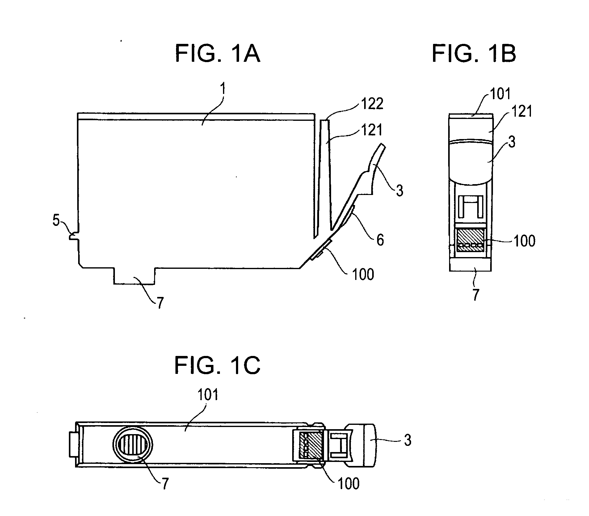
[0025]FIGS. 1A, 1B, and 1C are a side view, a front view, and a bottom view, respectively, of an ink tank that serves as a liquid container according to a first embodiment of the present invention. In the following description, a “front side” of the ink tank is defined as the side that faces a user to allow handling (e.g., attaching and detaching) of the ink tank and to provide information to the user (to emit light from a display unit, which will be described later).

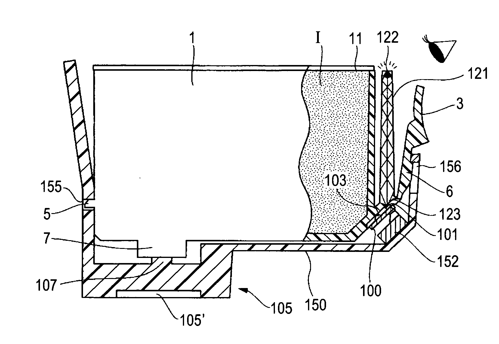
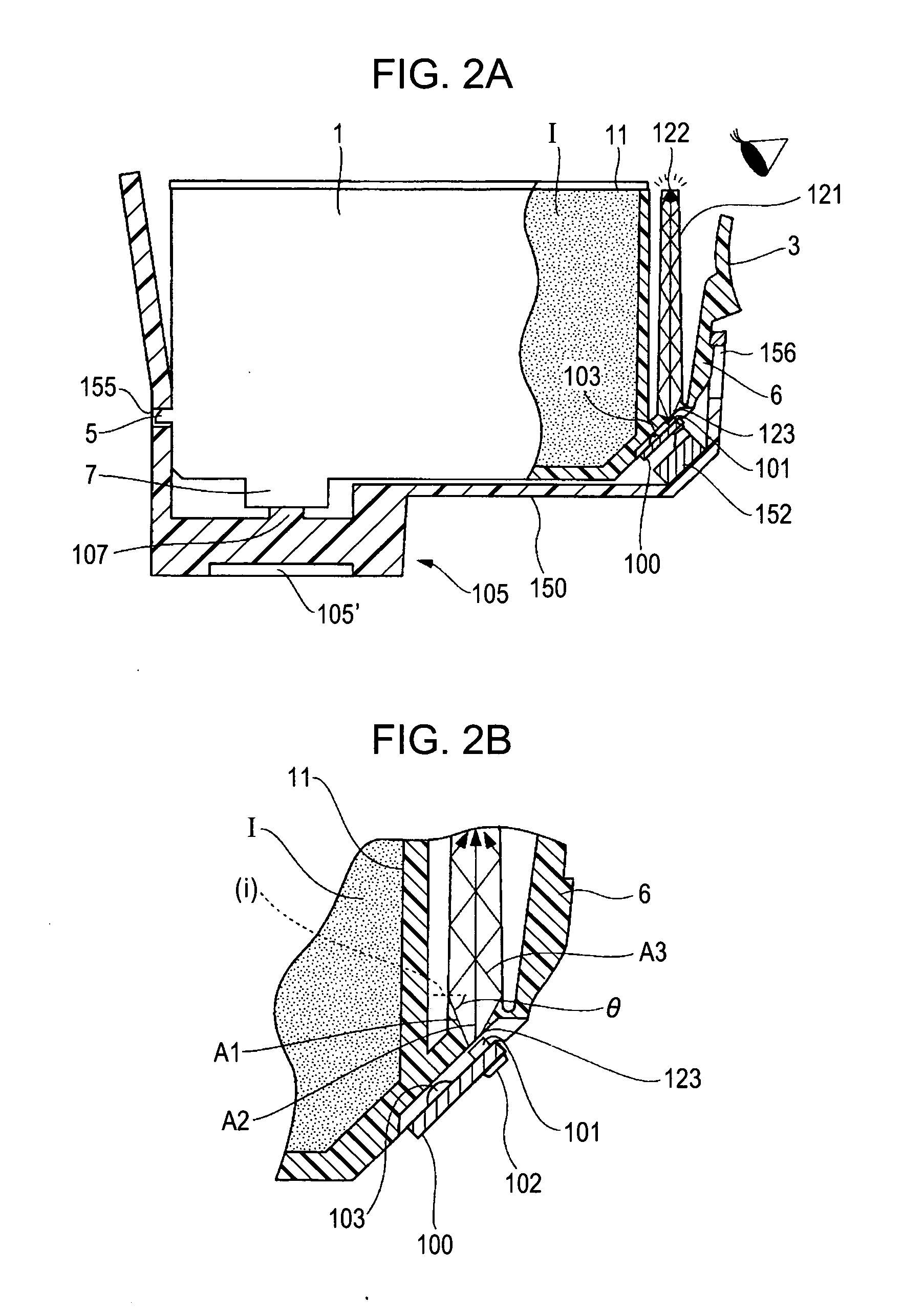
[0026] Referring to FIGS. 1A, B, and C, an ink tank 1 of the present embodiment has a support member 3 that is supported on the front side of the ink tank 1 at a lower region thereof. The support member 3 is made of resin and is integrated with an outer casing of the ink tank 1. The support member 3 can be moved around the supporting portion when the ink tank 1 is attached to a tank holder, which will be described below. The ink tank 1 has a first engaging portion 5 and a second engaging portion 6 that is integrated wi...

second embodiment

[0067] In the above-described first embodiment, the control circuit 300 in the printer main body controls the illumination of the LEDs (light-emitting elements) to present the information regarding the amount of ink remaining in each ink tank 1 or the like to the user. In addition, the control circuit 300 also performs a control process for reducing the variation in the amount of light emitted from the LEDs on the basis of the light-amount rank information stored in each ink tank 1. However, the control process for reducing the variation in the amount of light can also be performed by the control element in the IC package 103 included in each ink tank 1.

[0068] In the second embodiment according to the present invention, the control element in the IC package 103 included in each ink tank 1 performs the control process for reducing the variation in the amount of light emitted from the LEDs on the basis of the light-amount rank information stored in the storage element in the IC packa...


PUM


Abstract

A liquid container that can present various information using illumination of a light-emitting unit includes an IC package having a storage element and the light-emitting unit. The storage element stores information used for controlling the amount of light emitted from an LED included in the light-emitting unit, so that variation in brightness of the light-emitting unit can be reduced and the information can be adequately presented.

Description

BACKGROUND OF THE INVENTION [0001] 1. Field of the Invention [0002] The present invention relates to liquid containers for storing liquid, such as ink, and recording apparatuses using the liquid containers. More particularly, the present invention relates to a liquid container that can present various information using illumination of a light-emitting unit, such as a light-emitting diode (LED), and a recording apparatus using the liquid container. [0003] 2. Description of the Related Art [0004] Recently, as digital cameras have come into widespread use, a recording method called non-PC recording in which a digital camera is directly connected to a printer that serves as a recording apparatus to perform a recording operation without using a personal computer (PC) has become popular. In addition, another type of non-PC recording in which a card-shaped information storing medium for a digital camera is directly attached to a printer for data transmission to perform a recording operatio...

Claims


Application Information

Patent Timeline
Patent Type & Authority Applications(United States)
IPC IPC(8): B41J2/175
CPCB41J2/17546B41J2/17566B41J2002/17573
Inventor KITABATAKE, KENJIHAYASAKI, KIMIYUKIHATASA, NOBUYUKIOCHIAI, TAKAYUKIWATANABE, SHINJI
Owner CANON KK
Learn More