Method for reactivation of magnetic detection tag and machine for reactivation of magnetic detection tag
a magnetic detection tag and reactivation technology, applied in the mechanical actuation of burglar alarms, instruments, burglar alarms, etc., can solve the problems of complex structure of the reactivation machine, mechanical complexity, and malfunction at the driving section, and achieve low malfunction, simple structure, and reliable reactivation of the magnetic detection tag
- Summary
- Abstract
- Description
- Claims
- Application Information
AI Technical Summary
Benefits of technology
Problems solved by technology
Method used
Image
Examples
example 1
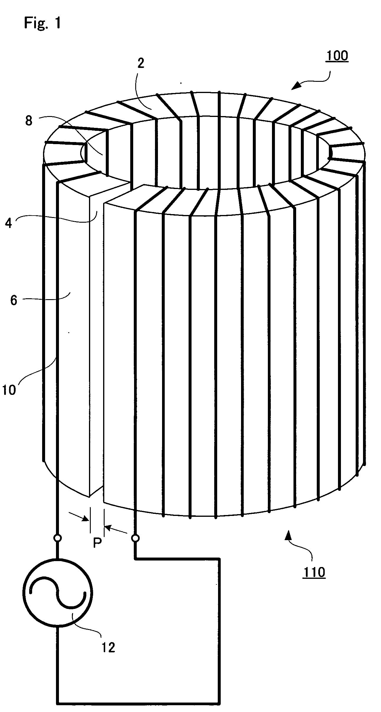
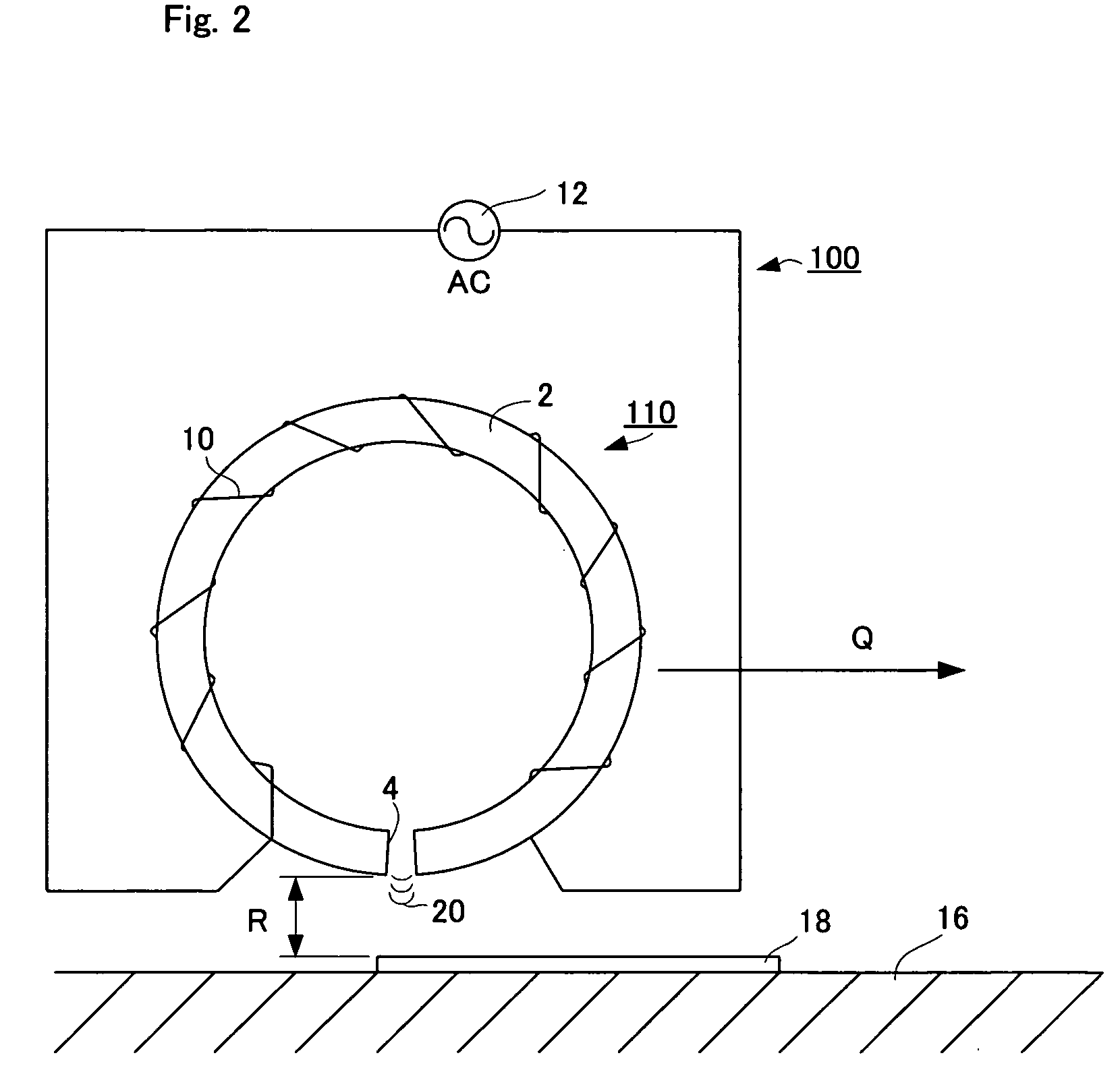
[0065] There were prepared two half-cylindrical ferrite cores obtained by dividing a cylindrical ferrite core of 25 mm in outer diameter, 12 mm in inner diameter and 30 mm in height, into two parts along a plane including the axial line of the core. A conductor of 0.35 mm in diameter was wound round each half-cylindrical ferrite core 100 times, to produce two coils. The two coils were combined in a cylindrical shape. In this case, at one contact portion of the two half-cylindrical ferrite cores, the divided end surfaces of the half-cylindrical ferrite cores were allowed to be apart from each other by 1 mm (a width P) to constitute a gap 4. At other contact portion, the two half-cylindrical ferrite cores were adhered to each other.
[0066] The conductors of the two coils were connected in series and the two ends of the connected conductor were connected to an AC power source. As a result, there was produced a reactivation machine having approximately the same structure as the reactiva...
example 2
[0089] Reactivation machines were produced in the same manner as in Example 1 except that the width P of gap was changed to 0.5 mm or 2.0 mm.
example 3
[0093] Coils shown in FIG. 8 were produced. Each of two plates [26 mm×12 mm×1 mm (thickness)] made of a permeability material (78% Permalloy PC produced by OHTAMA Co., LTD.) was bent parallel to the length 26 mm side at the center of plate of the length 12 mm to produce core plates 84a and 84b. The external angle of each bent portion was 40°.
[0094] As shown in FIG. 8, a copper conductor of 0.27 mm in diameter was wound round a U-shaped ferrite core main body 82 shown in FIG. 10 (trade name: Ferrite Core UI-25-35, width s of each core end s=6 mm, thickness r=6 mm, distance l between two ends of U-shaped core=13 mm, produced by TOMITA ELECTRIC Co., LTD.), at the two arm portions each 357 times. The two ends of the conductor were connected in series.
[0095] Then, to the two ends of the U-shaped ferrite core main body 82 were adhered the above-mentioned core plates 84a and 84b with an adhesive (an instantaneous adhesive produced by Henkel Japan Ltd., trade name: LOCTITE 401). The gap c...
PUM
 Abstract
Description
Claims
Application Information
 - R&D
- Intellectual Property
- Life Sciences
- Materials
- Tech Scout
- Unparalleled Data Quality
- Higher Quality Content
- 60% Fewer Hallucinations
Browse by: Latest US Patents, China's latest patents, Technical Efficacy Thesaurus, Application Domain, Technology Topic, Popular Technical Reports.
© 2025 PatSnap. All rights reserved.Legal|Privacy policy|Modern Slavery Act Transparency Statement|Sitemap|About US| Contact US: help@patsnap.com


