
Liquid sensing apparatus for a liquid container for supplying a liquid to a liquid consuming apparatus, and a liquid container in which the liquid sensing apparatus is built

a technology of liquid sensing apparatus and liquid container, which is applied in the direction of liquid/fluent solid measurement, instruments, machines/engines, etc., can solve the problems of affecting the sensing of the residual amount of liquid jet head and the damage of liquid jet head, and achieve accurate sensing the effect of the poin

Active Publication Date: 2006-06-29
SEIKO EPSON CORP
View PDF7 Cites 16 Cited by
  • Summary
  • Abstract
  • Description
  • Claims
  • Application Information

AI Technical Summary

Benefits of technology

The present invention provides a liquid sensing apparatus that can accurately sense the point of time when a liquid level reaches a specified level, while suppressing evaporation of the liquid as small as possible. The apparatus includes a liquid reservoir portion, a movable member, a recess portion, and a piezoelectric sensing means. The recess portion can form a closed space when the movable member reaches a predetermined position. The apparatus can be used in a liquid container to sense the level of liquid remaining. The invention also includes various methods for applying a vibration to the recess portion and sensing the resulting free vibration. The invention can provide a more accurate and reliable liquid level sensing apparatus for various applications.

Problems solved by technology

If the liquid jet head is operated without the supply of the liquid, the liquid jet head is damaged by the so-called blank shot.
This proposal can sense the remaining liquid amount with relatively high accuracy, but suffers from a problem in that sensing of the residual amount of the ink contained in the flexible bag is affected by deflection, crease, or the like of the flexible bag because the rigid body is moved to follow a deformation of the flexible bag,

Method used


Image

  • Liquid sensing apparatus for a liquid container for supplying a liquid to a liquid consuming apparatus, and a liquid container in which the liquid sensing apparatus is built
  • Liquid sensing apparatus for a liquid container for supplying a liquid to a liquid consuming apparatus, and a liquid container in which the liquid sensing apparatus is built
  • Liquid sensing apparatus for a liquid container for supplying a liquid to a liquid consuming apparatus, and a liquid container in which the liquid sensing apparatus is built

Examples


Embodiment Construction

[0056] The details of the present invention will be explained with reference to illustrated embodiments hereinafter.

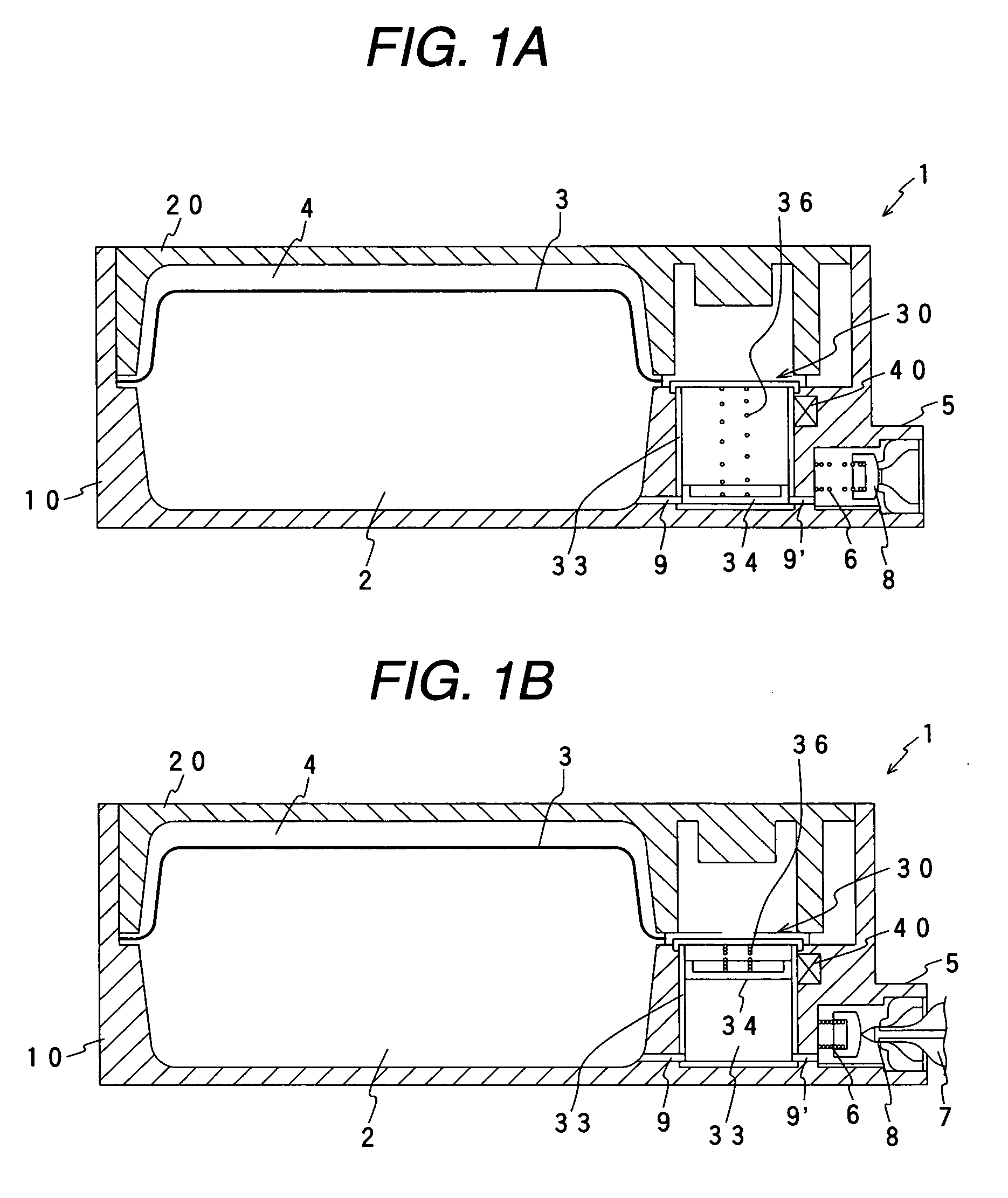
[0057]FIGS. 1A and 1B are schematic views showing an embodiment of a liquid container of the present invention, respectively, by taking an ink cartridge, which contains the ink to be supplied to an ink jet recording apparatus as a liquid consuming apparatus, as an example.

[0058] In this embodiment, a first case 10 and a second case 20, each constructed by a box member forming a semi-shell body, are combined together into a case to form a cartridge 1 serving as a liquid container. In order to form a liquid reservoir region 2 that contains the liquid such as an ink, a flexible film member 3 formed of a resin film, or the like is welded to a periphery of the first case 10 by the thermal welding, or the like and sealingly covers an opening portion formed in the first case 10. Also, a periphery of the second case 20 is pressure-contacted with the thermally welded portion ...


PUM


Abstract

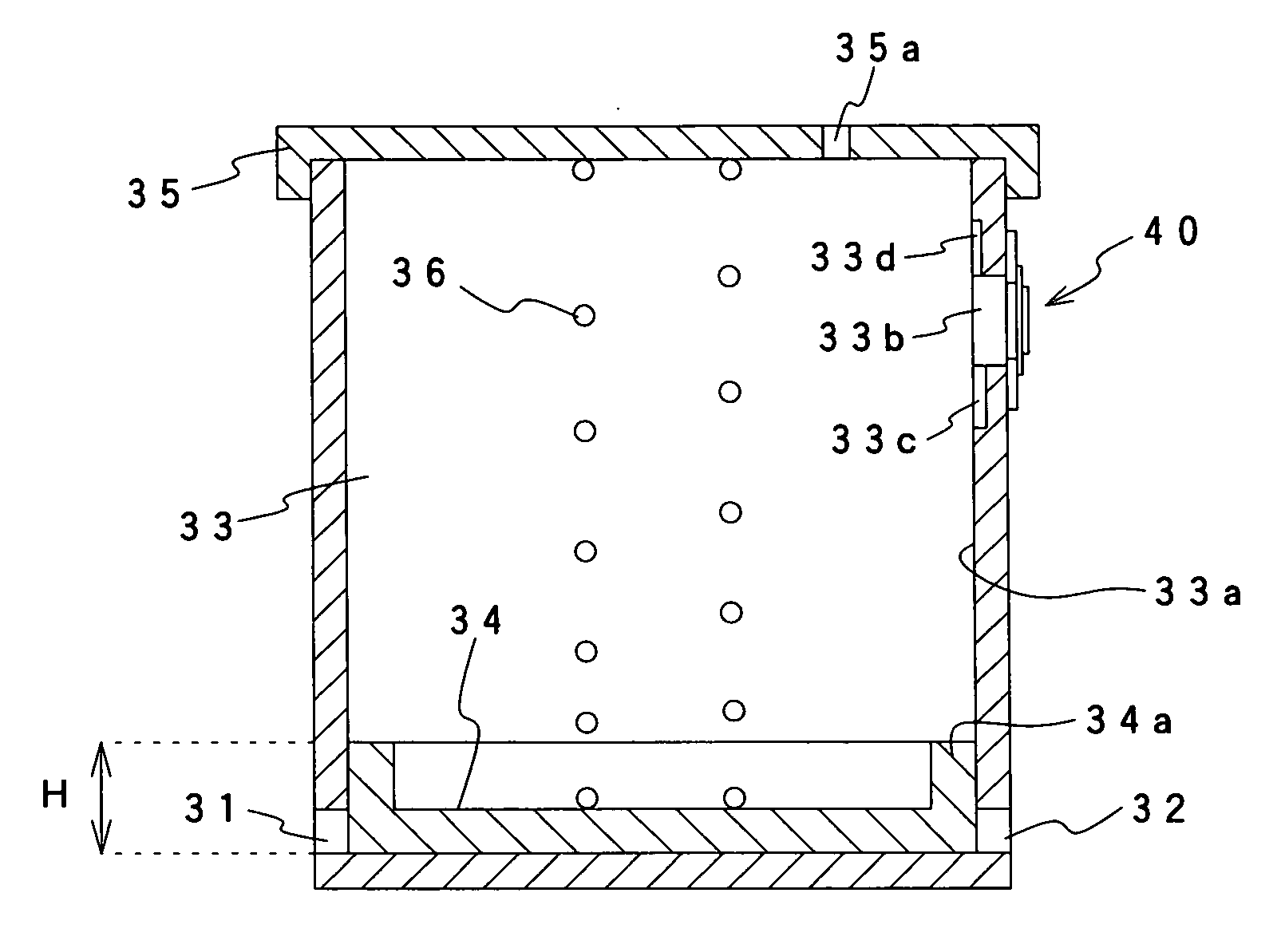
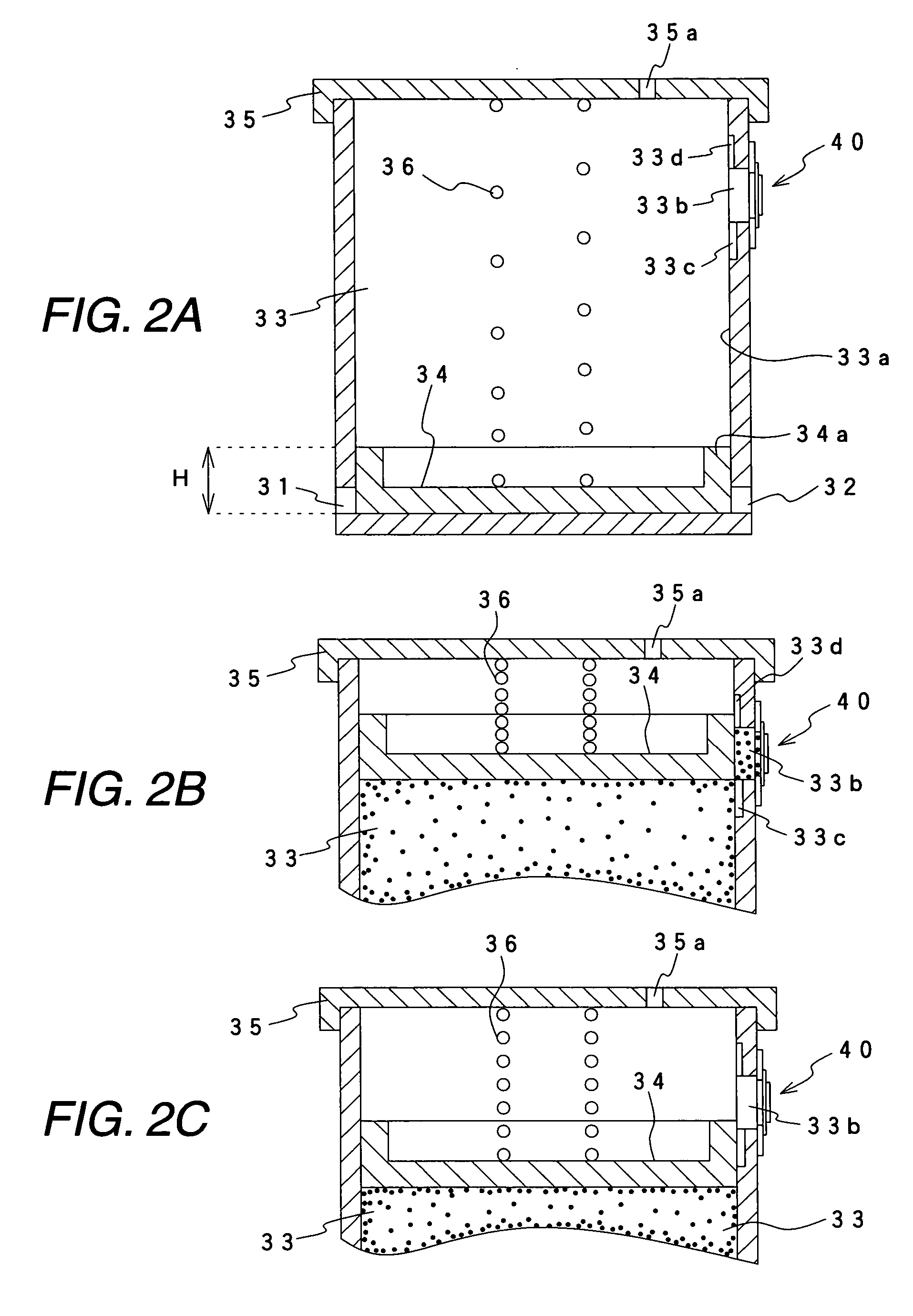
A liquid sensing apparatus includes a liquid sensing chamber 33 having a liquid inlet port that is in communication with an external liquid container in which a liquid is reserved, and a liquid outlet port that is in communication with a liquid consuming apparatus, a movable member 34 movable depending on a liquid level in the liquid sensing chamber 33, a recess portion 33b, 41a for cooperating with a wall surface of the movable member 34 to form a closed space when the movable member 34 is moved to a predetermined position depending the liquid level, and a piezoelectric sensing means 40 for applying a vibration to the recess portion and sensing a state of a free vibration following upon the vibration.

Description

BACKGROUND OF THE INVENTION [0001] The present invention relates to a liquid container for supplying a predetermined liquid to a liquid consuming apparatus, such as a liquid jet head, for jetting a minute amount of droplet, or the like and, more particularly, the technology to sense a residual amount of the liquid. [0002] A liquid jet head of a commercial recording apparatus for super-high quality printing as well as liquid jet heads of a textile printing apparatus and a microdispenser receive a supply of a liquid from a liquid container. If the liquid jet head is operated without the supply of the liquid, the liquid jet head is damaged by the so-called blank shot. For this reason, a residual amount of the liquid in the liquid container must be monitored to prevent such damage. [0003] Taking the recording apparatus as an example, various methods of sensing a residual ink amount in an ink cartridge serving as the liquid container have been proposed. JP-A-2001-146030 proposes that a v...

Claims


Application Information

Patent Timeline
Patent Type & Authority Applications(United States)
IPC IPC(8): G01F23/00G01F23/28B41J2/175G01F23/296G01F23/70
CPCB41J2/17513B41J2/17566B41J2002/17516B41J2002/17583G01F23/0046G01F23/2967G01F23/70G01F23/0007B41J2/175B41J2/17
Inventor USUI, MINORUKOSHINO, KAZUOKIMURA, HITOTOSHI
Owner SEIKO EPSON CORP
Learn More