
Method of monitoring brain function

a brain function and brain function technology, applied in the field of mathematical models, can solve the problems of limited clinical ability of patients to measure and monitor brain function, and achieve the effect of improving clinical accuracy and reducing clinical risk

Active Publication Date: 2006-06-22
CORTICAL DYNAMICS
View PDF11 Cites 43 Cited by
  • Summary
  • Abstract
  • Description
  • Claims
  • Application Information

AI Technical Summary

Problems solved by technology

Therefore their ability to measure, and thus monitor, brain function in the clinical setting is limited.

Method used


Image

  • Method of monitoring brain function
  • Method of monitoring brain function
  • Method of monitoring brain function

Examples


Embodiment Construction

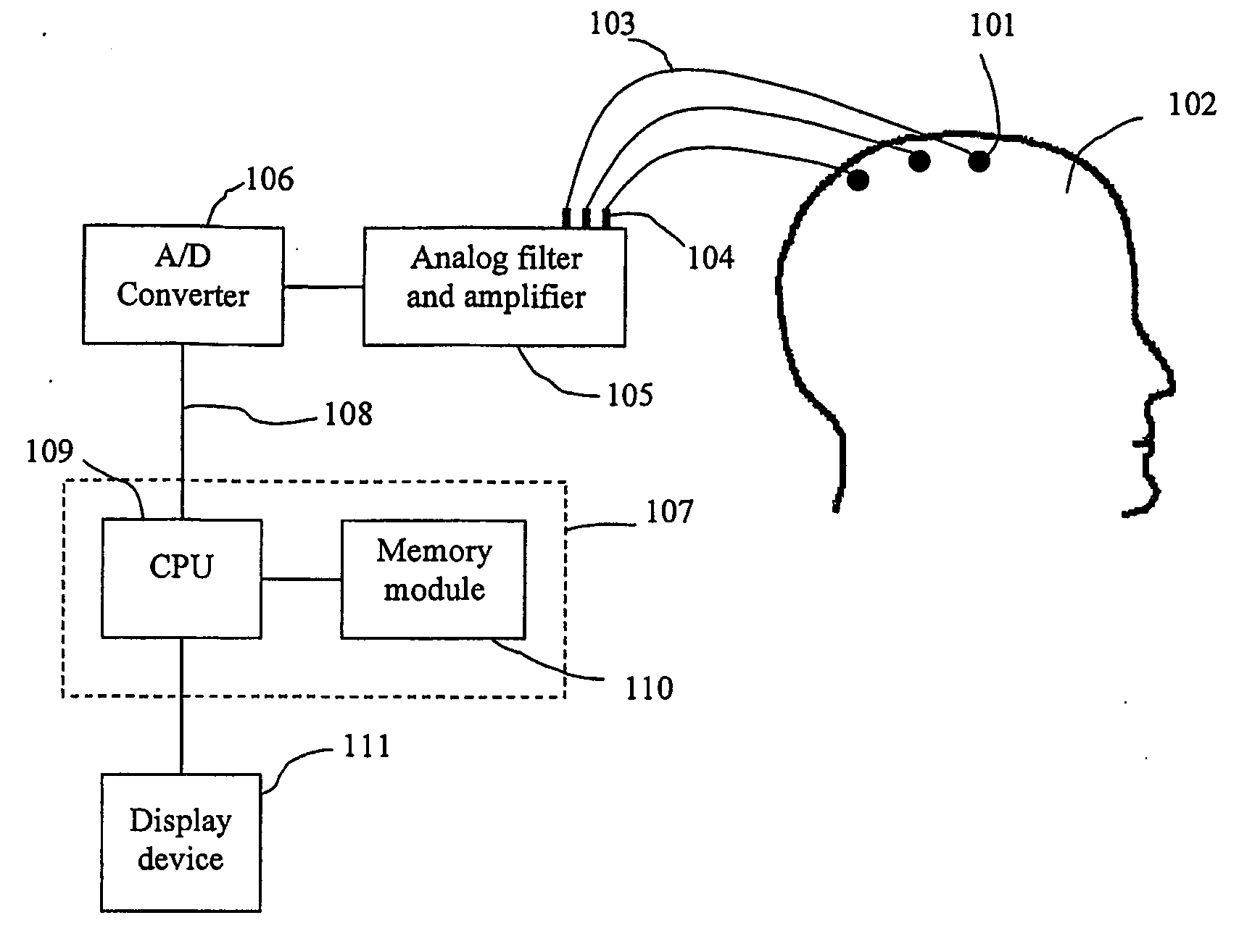
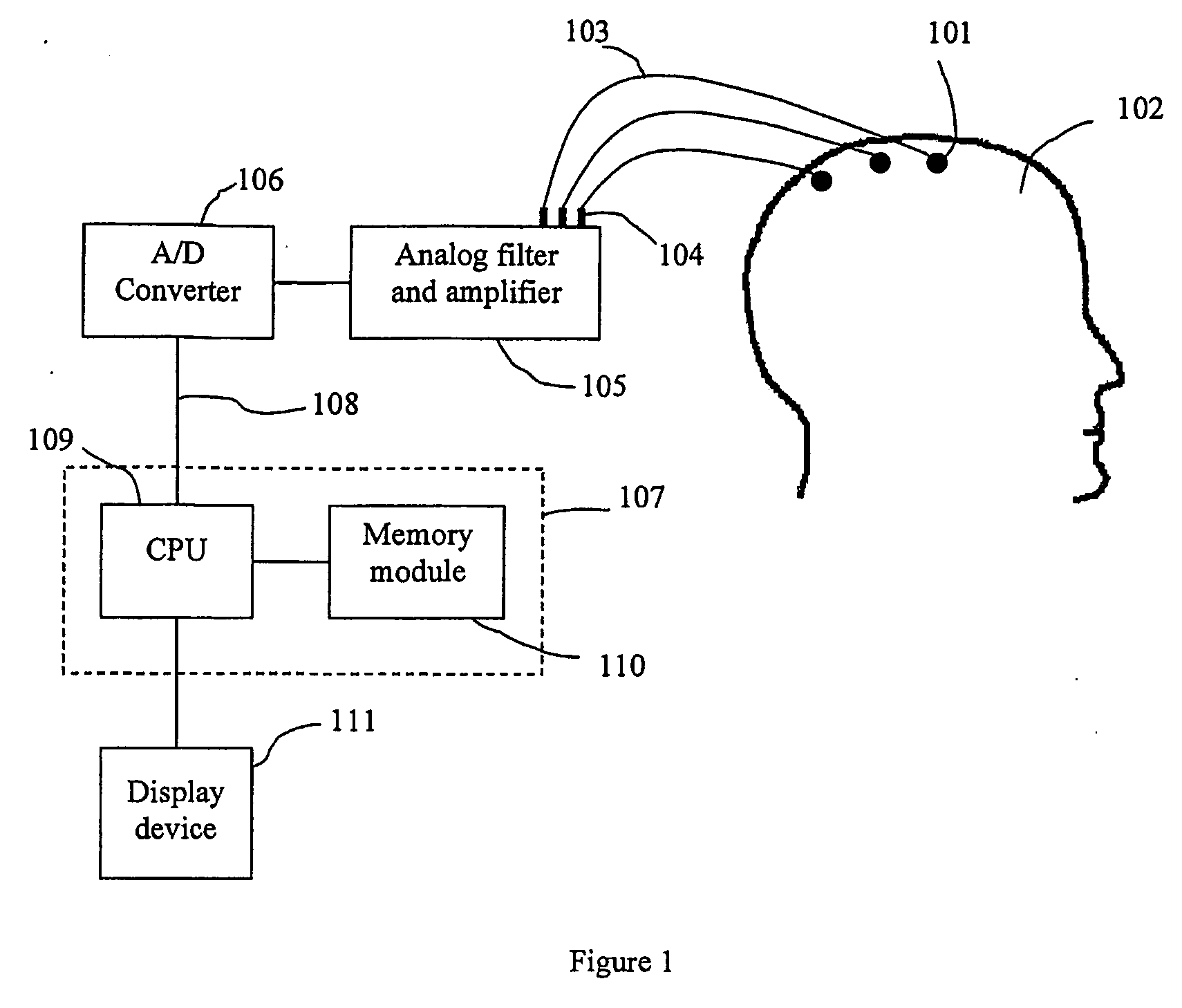
[0140]FIG. 1 is a diagram showing a preferred embodiment of the physical components of the system. The EEG signals are detected by multiple electrodes 101 from the scalp of a subject 102, where the electrodes are positioned preferably arranged according to the international 10:20 standard system with the addition of mid-point electrodes as necessary. Preferably, the EEG signals are recorded referenced to linked ears using 64 scalp electrodes attached to an electrode cap using the nasion as a ground. Other techniques for recording the EEG can also be used.

[0141] It is preferable that the EEG is analysed as a sequence of overlapping fixed length segments. This technique is further described with reference to FIG. 10. FIG. 10 shows an example of a typical EEG signal 201 recorded from a subject over a period of 10 seconds. To illustrate the preferred sampling technique, it is assumed that recorded EEG signals are digitised and segmented into fixed, overlapping, 2 second segments. The f...


PUM


Abstract

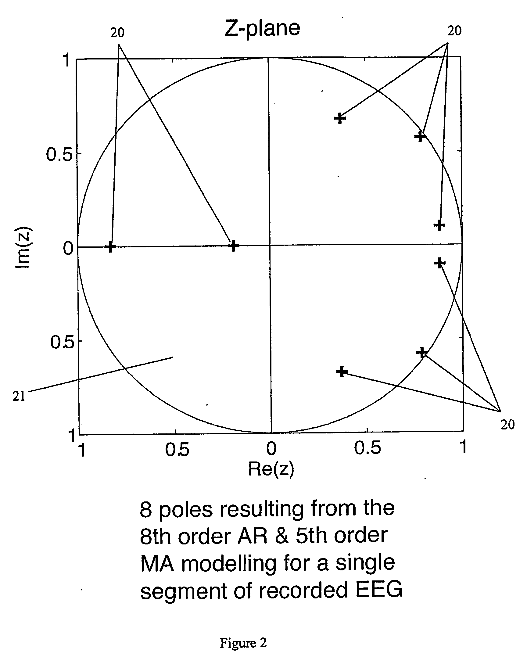
A method for assessing brain state by analysing mammalian brain electroencephalogram (“EEG”) recordings using an eighth order autoregressive and fifth order moving average discrete time equation.

Description

FIELD OF THE INVENTION [0001] The present invention relates to a method and system for the application of a mathematical model, and in particular a fixed order auto-regressive moving average model, to analyse electroencephalogram (“EEG”) signals generated by a subject in order to assess and monitor the subject's brain function under conditions of health, disease and therapeutic intervention. BACKGROUND OF THE INVENTION [0002] In clinical practice involving alterations in the level of consciousness, such as during the administration of sedatives or general anaesthetic agents, it is important to be able to quantify brain function. Most approaches rely upon the analysis of the brain's surface electrical activity, known as the electroencephalogram or EEG. In general the signal analysis method chosen is based on the statistical properties of the signal being analysed. The more closely matched the method used is to the signal properties, the more reliable, meaningful and accurate the resu...

Claims


Application Information

Patent Timeline
IPC IPC(8): A61B5/0476A61B5/374
CPCA61B5/048A61B5/4812A61B5/4821A61B5/374
Inventor LILEY, DAVID TIBOR JULIAN
Owner CORTICAL DYNAMICS
Learn More