
Light emitting device and the use thereof

a technology of light emitting devices and led assemblies, which is applied in the direction of semiconductor devices, basic electric elements, electrical appliances, etc., can solve the problems of inferior color rendering index (cri) of the second type of conventional led assemblies, large size of each led assembly, and large production cost of the led assembly. achieve the effect of reducing the size of the backlight modul

Inactive Publication Date: 2006-06-22
GENESIS PHOTONICS
View PDF4 Cites 13 Cited by
  • Summary
  • Abstract
  • Description
  • Claims
  • Application Information

AI Technical Summary

Benefits of technology

[0008] Therefore, it is an object of the present invention to provide a light emitting device which has a superior CRI, and which is applicable to a backlight module so as to reduce the size of the backlight module.

Problems solved by technology

However, in the first type of the conventional LED assembly, since three LEDs are required for each LED assembly, the size of each LED assembly is relatively large, and the production cost thereof is relatively high as well.
As for the second type of the conventional LED assembly, since the intensities of the red and green light portions are insufficient, the color rendering index (CRI) of the second type of the conventional LED assembly is inferior.
Furthermore, when the second type of the conventional LED assembly is used as a light source for a liquid crystal display, most of the yellow light portion cannot pass through a color filter, which merely permits red, blue, and green light to pass therethrough.
Therefore, illumination intensity of the liquid crystal display is insufficient.

Method used


Image

  • Light emitting device and the use thereof
  • Light emitting device and the use thereof
  • Light emitting device and the use thereof

Examples


Embodiment Construction

[0021] Before the present invention is described in greater detail, it should be noted that like elements are denoted by the same reference numerals throughout the disclosure.

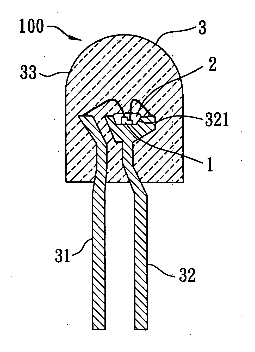
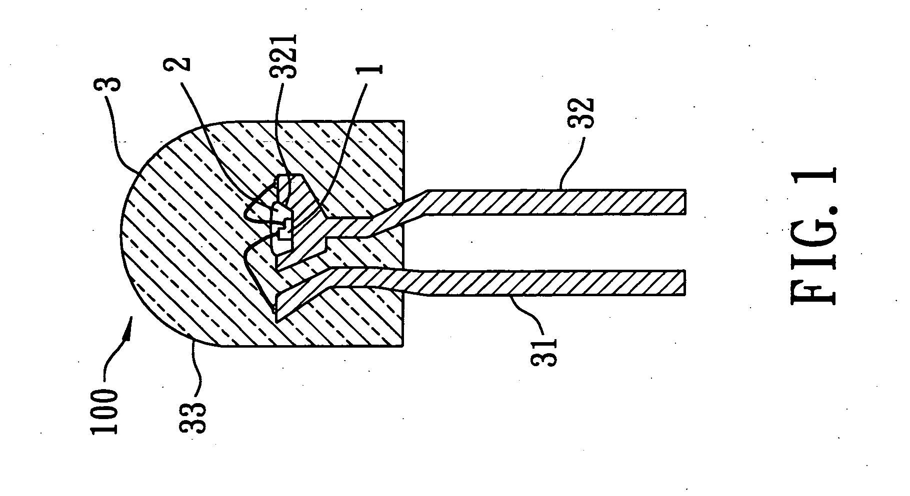
[0022] Referring to FIG. 1, the first preferred embodiment of a light emitting device 100 according to this invention is shown to include a die 1, a photostimulable luminescent substance 2, and a holding member 3.

[0023] The holding member 3 holds the die 1 and the photostimulable luminescent substance 2, and includes a first lead 31 electrically connected to the die 1, and a second lead 32 electrically connected to the die 1 and having a receiving recess 321 at a top end thereof. The first and second leads 31, 32 are substantially parallel to each other. In the preferred embodiment, the first lead 31 is a p-type electrode lead, and the second lead 32 is an n-type electrode lead. The die 1 is received in the receiving recess 321 of the second lead 32. The photostimulable luminescent substance 2 is filled in th...


PUM


Abstract

A light emitting device includes a die and a photostimulable luminescent substance. The die has a first semiconductor light-emitting layer emitting a first color light having a first wavelength range, and a second semiconductor light-emitting layer emitting a second color light having a second wavelength range different from the first wavelength range. The photostimulable luminescent substance is excitable by at least one of the first and second color lights to emit a third color light having a third wavelength range. The third color light is mixed with the first and second color lights to emit a light blend having a wavelength range covering the first, second, and third wavelength ranges.

Description

CROSS-REFERENCE TO RELATED APPLICATION [0001] This application claims priority of Taiwanese Application No. 093139372, filed on Dec. 17, 2004. BACKGROUND OF THE INVENTION [0002] 1. Field of the Invention [0003] The invention relates to a light emitting device, more particularly to a light emitting device applicable to a backlight module, a displayer, a luminescent device, and the like. [0004] 2. Description of the Related Art [0005] A first type of a conventional LED assembly for emitting white light includes a first LED emitting red light, a second LED emitting green light, and a third LED emitting blue light. The LED assembly can emit white light by combining the red, green, and blue lights, and adjusting the ratio of the light intensities of the first, second, and third LEDs. [0006] A second type of a conventional LED assembly for emitting white light includes a LED emitting blue light and a fluorescent material excitable by the blue light to emit a substantially yellow light. Th...

Claims


Application Information

Patent Timeline
Patent Type & Authority Applications(United States)
IPC IPC(8): H01L33/00H01L33/08H01L33/24H01L33/32H01L33/44H01L33/50H01L33/56H01L33/60H01L33/62
CPCH01L33/08H01L33/50H01L2224/48091H01L2224/48247H01L2224/48257H01L2924/00014
Inventor CHEN, CHENG-CHUAN
Owner GENESIS PHOTONICS
Learn More