Combination dryer and method thereof
a combination dryer and dryer technology, applied in the direction of drying machines, drying machines, light and heating equipment, etc., can solve the problems of inability to keep the laundry for a long time in the related art tumble dryer, the tangled portion of the laundry is not dried smoothly, and the combination dryer cannot be supplied for being built-in, so as to prevent the change of the interior environment for being built-in
- Summary
- Abstract
- Description
- Claims
- Application Information
AI Technical Summary
Benefits of technology
Problems solved by technology
Method used
Image
Examples
first embodiment
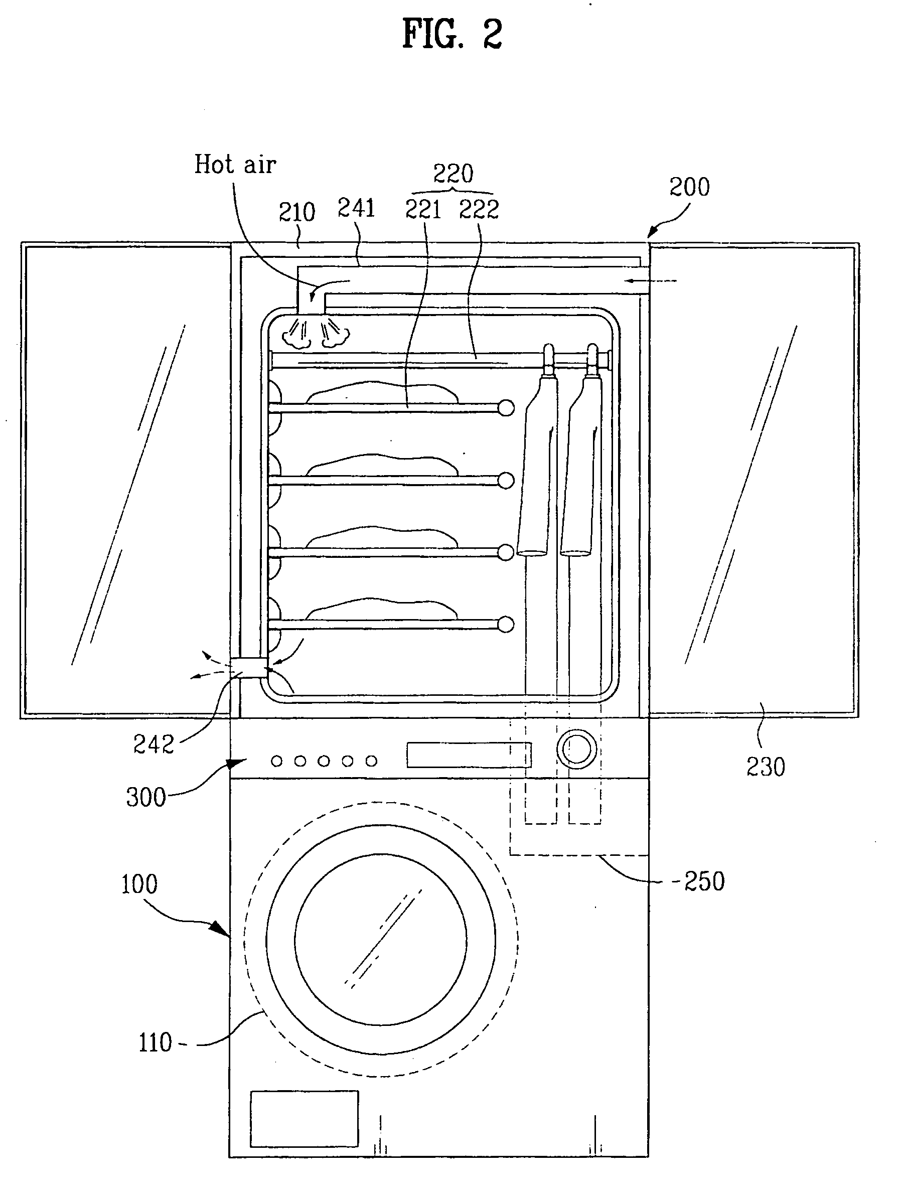
[0039] As shown in FIGS. 2 to 4, a combination dryer according to the present invention includes a tumble dryer 100, a cabinet dryer 200, and a controller 300.
[0040] The tumble dryer 100 performs only a drying cycle of the laundry. The tumble dryer 100 includes a drying drum 110 capable of rotating and agitating, a hot air supplying pipe, a hot air supplying part 130, and an air condensing part 140.
[0041] The hot air supplying pipe as a pipe guiding an inflow of high-temperature hot air is connectedly in communication with inside space of the drying drum 110, the air condensing part 140 and a cabinet dryer 200.
[0042] The hot air supplying pipe includes a first supplying pipe 121 for supplying hot air into the drying drum 110, a second supplying pipe 122 for receiving and supplying the air having passed through the air condensing part 140 to the first supplying pipe 121, and a third supplying pipe 123 for receiving and transmitting the air discharged from the drying drum 110 to the...
second embodiment
[0117] On the other hand, FIG. 8 shows a combination dryer according to the present invention.
[0118] That is, according to the second embodiment of the present invention, a steam generating part 310 is further provided for generating steam. Also, inner space of the steam generating part 310 and the cabinet dryer 200 is connected by a steam supplying pipe 320.
[0119] The steam generating part 310 supplies steam to the laundry kept within the cabinet dryer 200 to have the laundry refreshed, and is provided in at least one of the tumble dryer 100 and the cabinet dryer 200.
[0120] The steam generating part 310 includes a water chamber 311 for storing water to generate steam, a water supplying pipe 312 connected to the water chamber 311 for receiving water from the water chamber 311 a heating part 313 having predetermined space for storing the water received from the water supplying pipe 312, and heating element 314 provided within the heating part 313 for heating and evaporating the wat...
third embodiment
[0130] Therefore, a technical feature according to the present invention is that the condensed water generated in the air condensing part is used to generate steam.
[0131] That is, as shown in FIG. 9, according to a combination dryer of the third embodiment, a condensed water storing chamber 150 is further provided in the combination dryer of the first embodiment. The condensed water storing chamber 150 is connected to the air condensing part 140, the cabinet dryer 200 and the drain pipe 160.
[0132] The condensed water generated in the air condensing part 140 and in the cabinet dryer 200 is drawn into the condensed storing chamber 150 through the drain pipe 160.
[0133] Preferably, a pump 161 is further provided in the drain pipe 160 for forcibly pumping the condensed water to transmit the condensed water to the condensed water storing chamber 150.
[0134] Also, the combination dryer of the third embodiment further includes a steam generating part 410 for generating steam after receivi...
PUM
 Abstract
Description
Claims
Application Information
 - R&D
- Intellectual Property
- Life Sciences
- Materials
- Tech Scout
- Unparalleled Data Quality
- Higher Quality Content
- 60% Fewer Hallucinations
Browse by: Latest US Patents, China's latest patents, Technical Efficacy Thesaurus, Application Domain, Technology Topic, Popular Technical Reports.
© 2025 PatSnap. All rights reserved.Legal|Privacy policy|Modern Slavery Act Transparency Statement|Sitemap|About US| Contact US: help@patsnap.com


