
Abrasion resistant surface treatment method of a rotary member, runner, and fluid machine having runner

a technology of rotary members and fluid machines, which is applied in the direction of wind motors with parallel air flow, wind motors with perpendicular air flow, liquid fuel engine components, etc., can solve the problems of rotary members, pump surface abrasion, and washed out surfaces of runner, etc., to achieve high abrasion resistance, high treatment difficulty, and high crack resistance

Inactive Publication Date: 2006-06-15
EBARA CORP
View PDF4 Cites 6 Cited by
  • Summary
  • Abstract
  • Description
  • Claims
  • Application Information

AI Technical Summary

Benefits of technology

[0007] Another object of the invention is to provide an abrasion resistant surface treatment method in which surface treatment is performed on an area that meets a condition of either low treatment difficulty or high peripheral speed by a high speed flame spraying method; surface treatment is performed on an area with high treatment difficulty by a spraying and melting method or an arc spraying method, or a combination thereof, thus providing high abrasion resistance and high crack resistance.
[0008] A further object of the invention is to provide an abrasion resistant surface treatment method in which a further treatment method is applied to an area between the area in which a surface treatment by the high speed flame spraying method is performed and an area in which a surface treatment by the spraying and melting method is performed, thus further increasing the abrasion resistance and the crack resistance.

Problems solved by technology

A rotary member, such as a runner used in a turbine or a pump may suffer surface abrasion caused by some fluids used during operation.
However, for a runner of a hydraulic machine such as a turbine or a pump which handles water containing a large amount of sand and soil, a surface of the runner is washed out by fine particles of the sand and soil in the water, and suffers abrasion at an early stage.
A runner that is used in a hydraulic machine such as a turbine used in a power plant built in a river containing a large amount of sand and soil, especially quartz components, suffers extreme abrasion, and becomes unusable at an early stage.
Thus, a rotary member such as a runner used under such an environment has been surface treated with an abrasion resistant material, but a conventional method cannot provide sufficient abrasion resistance.
Depending on types of turbines or pumps to be used, some runners have vanes of a complex shape, and surface treatment by depositing an abrasion resistant material is sometimes extremely difficult depending on spots to be treated.
For example, a Francis turbine runner has a complexly curved vane, and the vane is placed between two members, that is, a main plate (a hub or a crown) and a side plate (a shroud or a band), thus surface treatment of an inside of the runner is extremely difficult.
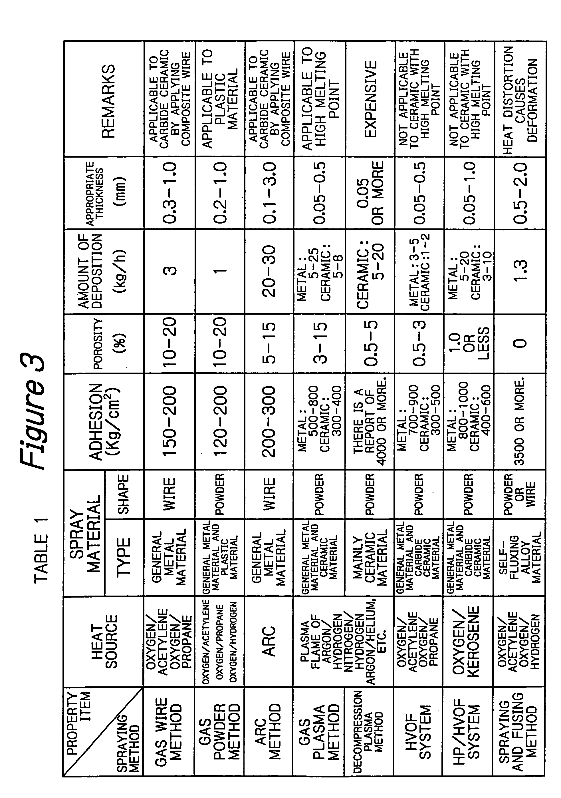
The inventor studied whether these methods can be applied to abrasion resistant surface treatment of a runner, and found that sprayable materials are limited by differences in heat sources, or the like.
This causes differences in abrasion resistance of treated surfaces, and further limits locations where the surface treatment can be performed depending on spraying methods.

Method used


Image

  • Abrasion resistant surface treatment method of a rotary member, runner, and fluid machine having runner
  • Abrasion resistant surface treatment method of a rotary member, runner, and fluid machine having runner
  • Abrasion resistant surface treatment method of a rotary member, runner, and fluid machine having runner

Examples


Embodiment Construction

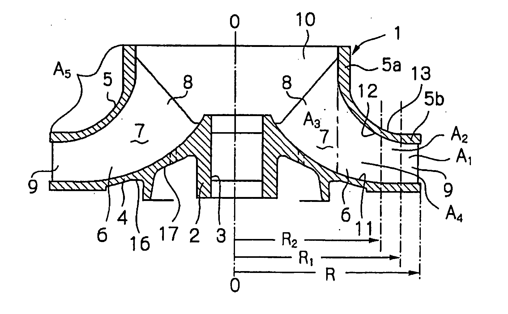
[0022] Now, an abrasion resistant surface treatment method according to the invention will be described with reference to the drawings, taking surface treatment of a runner of a pump as an example.

[0023]FIGS. 1 and 2 show a runner 1 of a pump in which the abrasion resistant surface treatment method is carried out. The runner 1 includes a hub 2 formed with a shaft hole 3 that receives a rotary shaft, a disk-like main plate 4 radially extending outward from the hub 2, an annular side plate 5 axially (vertically in FIG. 2) spaced from the main plate 4, and a plurality of vanes 6 which are circumferentially (circumferentially around an axis O-O in the shaft hole) and uniformly spaced between the main plate 4 and the side plate 5. The vanes are curved along a desired curved surface and integrally formed with the main plate and the side plate. The main plate 4, the side plate 5 and the vanes 6 define passages 7 through which a fluid passes. A radially inner portion 8 of the passage 7 is ...


PUM

PropertyMeasurementUnit
thickaaaaaaaaaa
thickaaaaaaaaaa
speedaaaaaaaaaa

Abstract

The invention provides a method for performing abrasion resistant surface treatment on a surface of a rotary member. The abrasion resistant surface treatment method is characterized by including steps of: dividing the surface of the rotary member into a plurality of areas A1, A2 depending on peripheral speed or treatment difficulty in surface treatment of the rotary member 1; spraying an abrasion resistant material on a surface of a first area where the peripheral speed is the highest, or the treatment difficulty is low, by a high speed flame spraying method; and spraying an abrasion resistant material on a surface of the second area with high treatment difficulty, by an arc spraying method.

Description

TECHNICAL FIELD [0001] The present invention relates to an abrasion resistant surface treatment method, a rotary member treated by the treatment method, and a fluid machine including the rotary member, and more particularly to a surface treatment method in which an area to be treated is divided into a plurality of areas in view of a peripheral speed of a rotary member and treatment difficulty in abrasion resistant surface treatment, and wherein an abrasion resistant material is deposited on a surface of the rotary member by a treatment method appropriate for each area, a runner as a rotary member having surfaces treated by the method, and a fluid machine including the runner. BACKGROUND ART [0002] A rotary member, such as a runner used in a turbine or a pump may suffer surface abrasion caused by some fluids used during operation. When a clean liquid, that is, a liquid containing few particulates is used, surface abrasion of a runner is not a significant problem except for surface ab...

Claims


Application Information

Patent Timeline
Patent Type & Authority Applications(United States)
IPC IPC(8): F03B3/12C23C4/12C23C4/123C23C4/129C23C4/131F04D29/02F04D29/22
CPCC23C4/00F04D29/026F04D29/2294F05D2230/313F05D2230/311
Inventor NAKAHAMA, SHUHEINAKAHAMA, KAZUKOISHIDO, TORUTAKAHASHI, MASARUNAGASAKA, HIROSHI
Owner EBARA CORP
Learn More