Device and method for installing piston ring

a technology of a device and a piston, which is applied in the direction of metal-working hand tools, metal-working apparatus, assembly machines, etc., can solve the problems of reducing the control speed of the robot, reducing productivity, and misplacing the piston rings, and achieves high accuracy. the effect of performing

Inactive Publication Date: 2006-06-15
HIRATA & CO LTD
View PDF20 Cites 11 Cited by
  • Summary
  • Abstract
  • Description
  • Claims
  • Application Information

AI Technical Summary

Benefits of technology

[0011] Since the driving mechanism, the piston pressing member, and the guide member are provided on the basis of the base, and since the piston pressing member performs a centering action as described above, the piston and the piston ring can be highly accurately positioned in the horizontal and vertical directions with a simple structure and with ease. Hence, productivity is improved, and production costs are reduced.
[0028] According to this structure, the inner wall surface disposed apart from the piston obliquely downwardly approaches the piston, which holds the connecting rod and which is suspended downwardly in the vertical direction, and comes into contact with the piston at the stage of having moved downwardly in the vertical direction. Hence, horizontal positioning can be highly accurately performed while keeping the piston in a horizontal state without inclining the piston.

Problems solved by technology

However, in the device disclosed by this publication, if the piston is disposed in the concave part in a slightly inclined state when the piston is transferred to and positioned in the concave part of the guide member by means of the robot, the piston rings guided by the outer circumferential surface of the guide member do not become parallel to the ring grooves of the piston, and hence there is a fear that a mistake will occur in installing the piston rings.
Therefore, disadvantageously, there is a need to perform positioning in a horizontal direction and positioning in a vertical direction with high accuracy when the piston is positioned in the concave part, and productivity is reduced if the control speed of the robot is decreased.
However, in the device disclosed by this publication, since positioning is performed by a manual operation or by a handling device, such as a robot, when the piston is positioned in the concave part, a positioning problem occurs as in the above conventional device.
Additionally, disadvantageously, since the diameters of the piston rings are reduced through multiple stages, much time is consumed to reach the step of installing the piston rings, and productivity is reduced.

Method used


Image

  • Device and method for installing piston ring
  • Device and method for installing piston ring
  • Device and method for installing piston ring

Examples


Embodiment Construction

[0039] The best mode of the present invention will be hereinafter described with reference to the attached drawings.

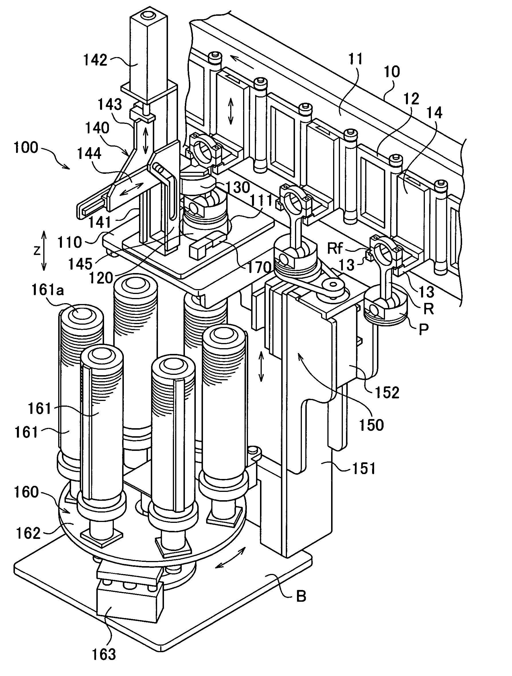
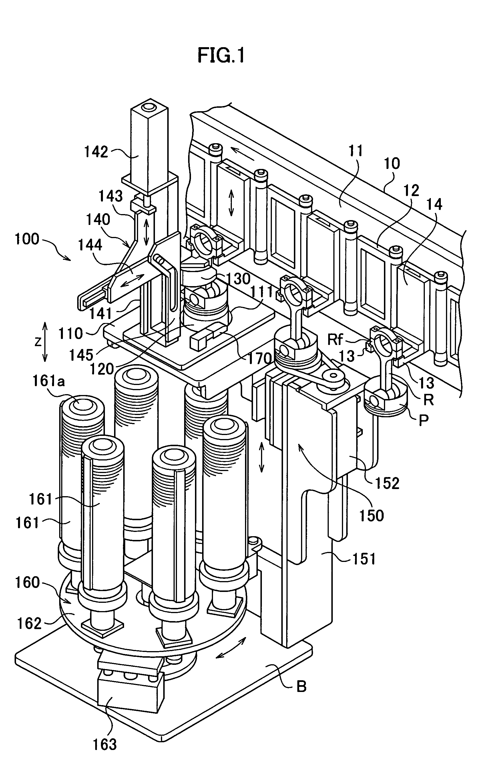
[0040] As shown in FIG. 1 to FIG. 3, a piston-ring-installing device includes a frame 10, a guide rail 11 that extends in a horizontal direction at the upper part of the frame 10, a conveyor 12 that is guided along the guide rail 11, and a piston-ring-installing unit 100 disposed under the conveyor 12.

[0041] The conveyor 12 is used to convey a piston P, to which a connecting rod R is connected, from a processing step performed on the upstream side in the flow of a sequence of operations to this installing step, and, after completing the installing step, continuously convey the piston P to a processing step performed on the downstream side. As shown in FIG. 1 to FIG. 3, the conveyor 12 has a plurality of pairs of holding arms 13 spaced with predetermined intervals, in order to position and hold flange parts Rf of the connecting rod R.

[0042] As shown in FIG. 1 to FIG....


PUM

PropertyMeasurementUnit
diameteraaaaaaaaaa
lengthaaaaaaaaaa
diametersaaaaaaaaaa

Abstract

A piston-ring-installing device of the present invention includes a base (110) having a through-hole (111); a guide member (120) disposed in the through-hole and fixed to the base, for positioning a piston in the vertical direction while receiving a head of the piston suspended downwardly in the vertical direction, and guiding a piston ring while widening a diameter of the piston ring by an outer peripheral surface of the guide member; a piston pressing member (130) disposed above the base and supported movably toward a concave part (121b) of the guide member, and having a tapered inner wall surface (131) widened downwardly so as to come into contact with an edge of an upper end of the piston; a driving mechanism (140) disposed on the base, the driving mechanism driving the piston pressing member at least in the vertical direction; and a ring feeding mechanism (150) that feeds the piston ring placed on the guide member upwardly. Hence, a piston-ring installing operation is swiftly performed, and productivity is improved.

Description

TECHNICAL FIELD [0001] This invention relates to a device and a method for installing a piston ring onto a piston of an internal combustion engine, and more particularly, to a device and a method for supplying and installing a piston ring from below onto a piston suspended and held downwardly in a vertical direction. BACKGROUND ART [0002] A piston reciprocating in a cylinder bore of an internal combustion engine has a plurality of ring grooves (for example, three ring grooves). For example, two compression rings (chiefly, a first ring that seals a combustion gas and a second ring that seals the combustion gas and adjusts a lubricant film) used to prevent a combustion gas from blowing through and an oil ring consisting of a plurality of components to adjust the lubricant film are fitted in these ring grooves. A connecting rod is swingably connected to the piston. [0003] A known conventional device for installing these piston rings is made up of a cylindrical guide member whose diamet...

Claims


Application Information

Patent Timeline
Patent Type & Authority Applications(United States)
IPC IPC(8): B23P15/10B23P19/08B23P21/00
CPCB23P19/088Y10T29/53904Y10T29/536Y10T29/53313Y10T29/49876Y10T29/53961
Inventor HARATAKE, KENICHI
Owner HIRATA & CO LTD
Why Eureka
Try Eureka