
Boot band

a technology of boot bands and flexors, applied in the direction of hose connections, snap fasteners, buckles, etc., can solve the problems of troublesome clamping operation, adversely affecting workability, and insufficient time needed for clamping operation, so as to prevent buckling and shorten the length of the band body. , the effect of reducing the length of the band body

Active Publication Date: 2006-06-15
NHK SPRING CO LTD
View PDF2 Cites 5 Cited by
  • Summary
  • Abstract
  • Description
  • Claims
  • Application Information

AI Technical Summary

Benefits of technology

[0013] In contrast, in the second conventional boot band 2, shown in FIGS. 13 and 14, because the terminal end 29 is inserted into the engagement hole of the second boot-band pawl 22, the operation of pressing the outer-layer portion 4 inward is not necessary. Therefore, clamping can be performed by only one action, and clamping workability is improved in comparison with that of the first conventional boot band 1.
[0070] In the invention of Claim 4, by forming a rib as the reinforcing part, the reinforcing part can be formed easily.

Problems solved by technology

As such, two actions—one in the circumferential direction, and one inward—are necessary at the time of clamping, which makes the clamping operation troublesome.
In addition, because two actions are necessary, there is the following problem: the time needed for a clamping operation is needlessly long, which adversely impacts workability.

Method used


Image

  • Boot band
  • Boot band
  • Boot band

Examples


embodiment 1

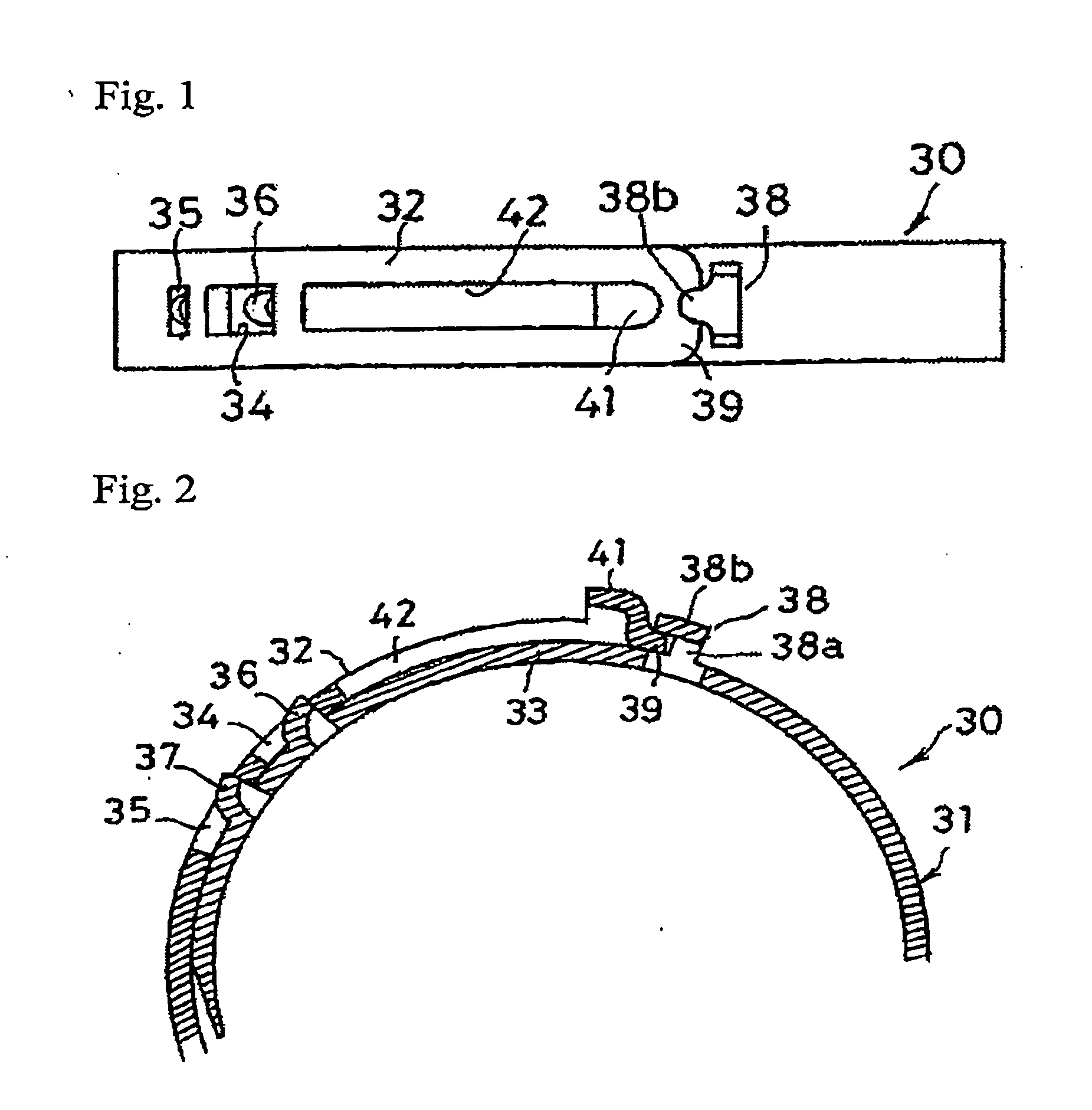
[0108]FIGS. 1 and 2 show a boot band 30 in Embodiment 1 of the present invention, which is formed with a belt-like band body 31.

[0109] The band body 31 is formed by press-punching a thin metallic plate into the form of a belt that is used for clamping a member to be clamped (not shown) under the condition that the band body 31 is wound—in the shape of a belt or a ring—around the member to be clamped. The band body 31, which is wound like a ring, is formed with an outer-layer portion 32 that overlaps an inner-layer portion 33, and, as described below, these outer-layer and inner-layer portions 32, 33 are pressed in the diameter-reducing direction, so as to clamp the member to be clamped.

[0110] A first boot-band pawl 41 is formed on the top of the end section (free end side) of the outer-layer portion 32 of the band body 31 so as to rise outward in the radial direction. Also, the terminal end 39 extends in the longitudinal direction of the free end, which is located nearer to the to...

embodiment 2

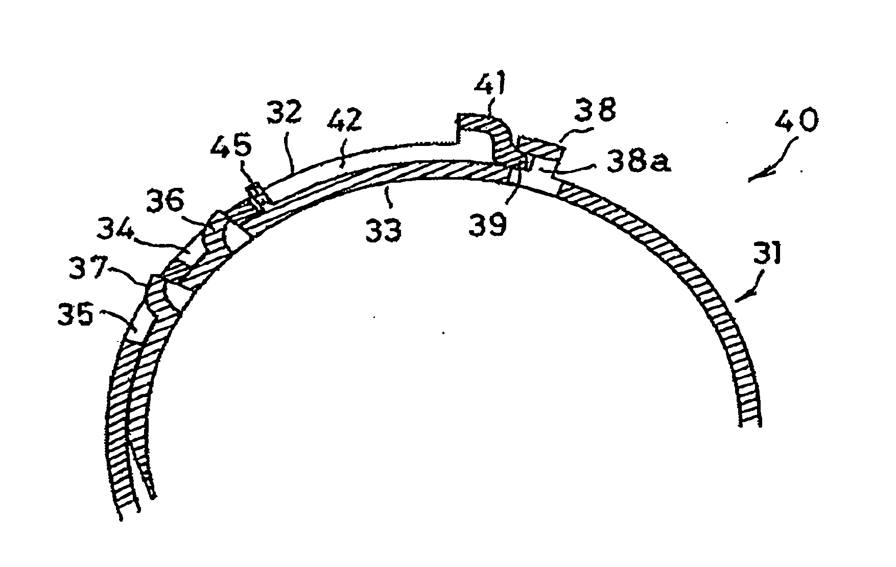
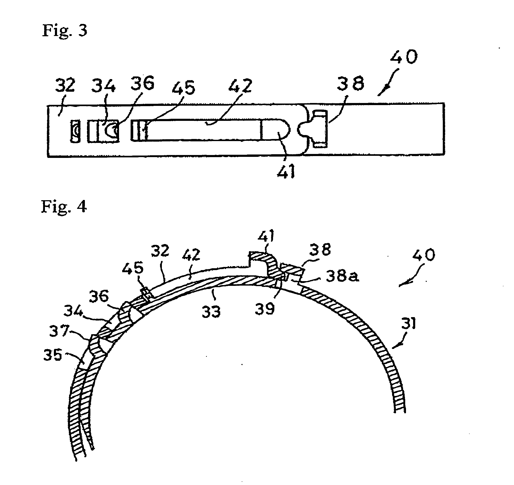
[0119]FIGS. 3 and 4 show Embodiment 2 of the present invention. The boot band 40 in this embodiment is provided with a temporary-tacking pawl 45 in addition to the elements of the boot band 30 in Embodiment 1.

[0120] In this embodiment, a temporary-tacking pawl 45 is formed in the inner-layer portion 33, near the engagement pawl 36 and between the second boot-band pawl 38 and the engagement pawl 36. The temporary-tacking pawl 45 is formed so as to rise from the above-mentioned portion of the inner-layer portion 33 outward in the radial direction, and its width is such that it is insertable into the slit 42 of the outer-layer portion 32. When the band body 31 is wound like a ring, the temporary-tacking pawl 45 is inserted into and engaged with the slit 42 of the outer-layer portion 32. Such engagement makes possible a temporarily-tacked ring-like condition of the band body 31.

[0121] In such an embodiment, when the temporary-tacking pawl 45 is inserted into and engaged with the slit ...

embodiment 3

[0123]FIGS. 5 and 6 show Embodiment 3 of the present invention. In this embodiment, a rib 47 is formed as a reinforcing part on the boot band 50.

[0124] The rib 47 is formed between the second boot-band pawl 38 and the engagement pawl 36 in the inner-layer portion 33 of the boot band. In this embodiment, the rib 47 is formed with two parallel thin protrusion bars rising outward in the radial direction. The parallel rib 47 is formed in the circumferential direction so as to have approximately the same length as that between the second boot-band pawl 38 and the engagement pawl 36.

[0125] The rib 47 is formed as a reinforcing part so that the rigidity of the boot band 50 between the second boot-band pawl 38 and the engagement pawl 36 in the inner-layer portion 33 becomes large, and so that the cross-sectional second moment also becomes large. Because a load that generates buckling is proportional to the cross-sectional second moment, even if such a load—by which the outer-layer portion...


PUM


Abstract

Buckling is prevented at the time of clamping a band body, and the band body is made short. A boot band comprises a band body 31 that is wound in a ring shape—around a member to be clamped—in such a way that the outer-layer portion 32 of the band body 31 overlaps the inner-layer portion 33 of the band body 31, engagement holes 34, 35 that are formed in the outer-layer portion 32, engagement pawls 36, 37 that are formed on the inner-layer portion 33 and that are to be engaged with the engagement holes 34, 35, so that the band body 31 is maintained in a clamped condition, a first boot-band pawl 41 that is formed on the to and at the end of the outer-layer portion 32, a planar end 39 that is formed closer to the end of the outer-layer portion 32 than the first boot-band pawl 41 is, a second boot-band pawl 38 that (1) is formed in the inner-layer portion 33, (2) has (a) an opening 38a wherein the terminal end 39 can be inserted, and (b) a pressing portion 38b for pressing—from the outside—the terminal end 39 that is inserted in the opening 38a, and (3) clamps the band body 31 together with the first boot-band pawl 41, and a slit 42 that is formed between the first boot-band pawl 41 and the engagement hole 34 in the outer-layer portion 32.

Description

FIELD OF THE INVENTION [0001] This invention relates to a boot band for clamping and fixing on another member a tube-like or boot-like member made of rubber, resin, or the like. BACKGROUND OF THE INVENTION [0002] A boot band is used, for example, to clamp a boot that covers the power transmission of an automobile, so that (1) internal grease and the like are prevented from flowing out from the boot, and (2) water and foreign matter are prevented from infiltrating into the boot. Also, because the boot band is used to clamp the member to be clamped under the condition that the boot band is wound around the member to be clamped, one pair of boot-band pawls are provided on the boot band so that a clamping tool can be hooked onto the boot-band pawls to clamp the boot band. [0003]FIGS. 11 and 12 show a first conventional boot band 1 (see Patent Document 1), and FIGS. 13 and 14 show a second conventional boot band 2 (see Patent Document 2). The boot band 1 or 2 consists of a band body 3 ma...

Claims


Application Information

Patent Timeline
Patent Type & Authority Applications(United States)
IPC IPC(8): A43C11/00B65D63/02F16B2/08F16L33/035
CPCA43C11/00B65D63/02Y10T24/21F16L33/025Y10T24/1457F16L33/035F16B2/08
Inventor OGINO, TAKASHI
Owner NHK SPRING CO LTD
Learn More