
Method for composite packet-switching over WDM by transparent photonic slot routing

a technology of transparent photonic slot and composite packets, applied in the field of optical communication systems, can solve the problems of inability to reconfigure wavelength add-drop multiplexers at an adequate speed, loss of chlamtac, intrinsic loss of power splitters, etc., and achieve the effect of increasing network reconfigurability and provisioning ability

Inactive Publication Date: 2006-06-08
BORODITSKY MIKHAIL +1
View PDF2 Cites 3 Cited by
  • Summary
  • Abstract
  • Description
  • Claims
  • Application Information

AI Technical Summary

Benefits of technology

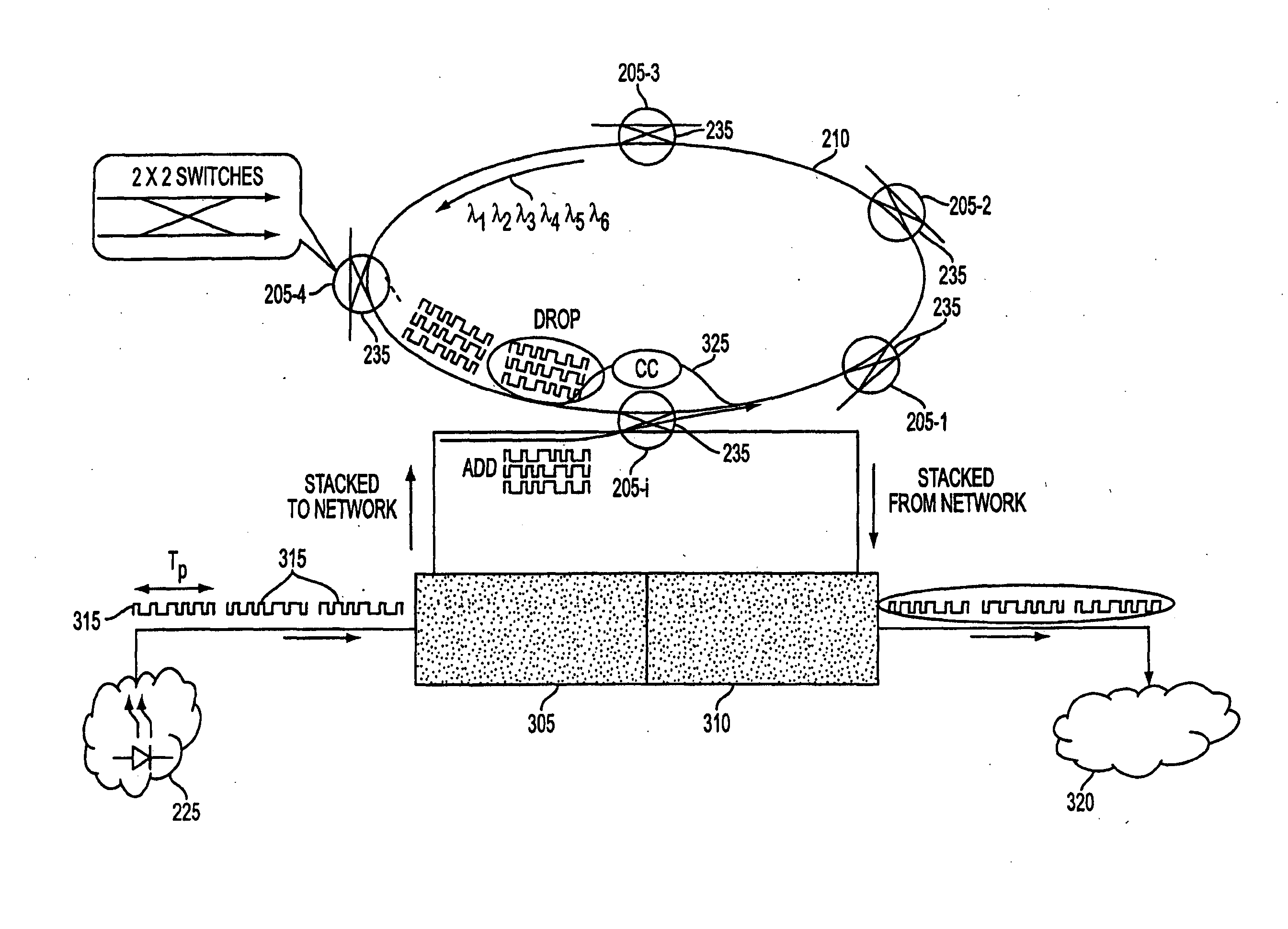
[0008] Photonic slot routing combines the features of both packet-switched (e.g., TDM) and WDM to achieve extremely high connectivity and flexibility while at the same time addressing the limitations of existing photonic switching technologies.
[0010] The system and method described herein provides high connectivity by optical means when using a single laser source at a given node. This can be an economical solution for regional or local IP networks, which require high connectivity rather than high throughput. Such a solution would lower the initial installment costs for a metro network in the service space, permitting optical network providers to grow packet-based networks modularly with lower marginal costs than previously permitted. That is, capacity can be gradually increased by the addition of more lasers at each node. The system evolves modularly with demand. Thus, as the number of lasers is increased as needed to fill slots with data, the wavelength-independent switch passes more and more wavelengths. The system is intrinsically blind to format and to rate upgrades (as long as the packet time is kept constant) and the upgrades can be introduced on a “pay-as-you-go” basis. An IP-friendly WDM architecture insures a more efficient integration with IP networks. This reduces the system constraints down to an irreducible set: the packet length, the transparency of the switch nodes, and the bandwidth of the optical components in the system. Finally, the use of reconfigureable optical devices such as tunable fiber Bragg gratings (FBGs) further increases network reconfigurability and provisioning ability.
[0012] An object, therefore, of the present invention is to provide a modular, cost-effective method for generating, switching and routing composite packets.
[0013] It is a further object of the present invention to provide high connectivity and bandwidth re-utilization using wavelength independent n×n optical switches on an optical ring network.
[0015] A further object of the present invention is to increase network reconfigurability and provisioning ability through the use of tunable filter.

Problems solved by technology

Nevertheless, while telecommunication networks are evolving towards packet-switching, WDM systems still remain largely circuit-switched.
While tunable Distributed Bragg Reflector (DBR) lasers with nano-second wavelength tuning speed and fast wavelength insensitive optical switches with gigahertz responses are becoming commercially available, there seems to be no current cost-effective way to reconfigure wavelength add-drop multiplexers at an adequate speed.
The system proposed by Chlamtac is lossy because Chlamtac uses power splitters since there are no Optical Add / Drop Multiplexers (OADMs), capable of operating at an adequate speed and power splitters are intrinsically lossy.
That is, there is admission loss when the power splitters add channels.
There is a significant under-utilization of the tunable lasers in the system proposed by Chlamtac because the lasers are used to generate only one packet at one wavelength.
There is a further necessity for the core optical ring in Chlamtac's proposed system to synchronize with a subtending ring, which is problematical in light of the optical buffers required by a subtending ring.
The problem is exacerbated because there can be multiple subtending rings in the network, each of which require optical buffering.
If the first node of a subtending ring removes a packet of the composite packet and adds another packet to the packet, then a subsequent node on the subtending ring can read or inspect the added packet, which means that privacy is lost.
This privacy loss may be unacceptable for certain applications.
The proposal described by Chlamtac also does not provide a way of dropping a part of an optical composite packet from the core ring.
Separate lasers are needed to generate different wavelengths, which means under-utilization of resources, and no implementation of the stacking means described herein was proposed.
Finally, the ability to tune the add / drop filters was not envisioned.

Method used


Image

  • Method for composite packet-switching over WDM by transparent photonic slot routing
  • Method for composite packet-switching over WDM by transparent photonic slot routing
  • Method for composite packet-switching over WDM by transparent photonic slot routing

Examples


Embodiment Construction

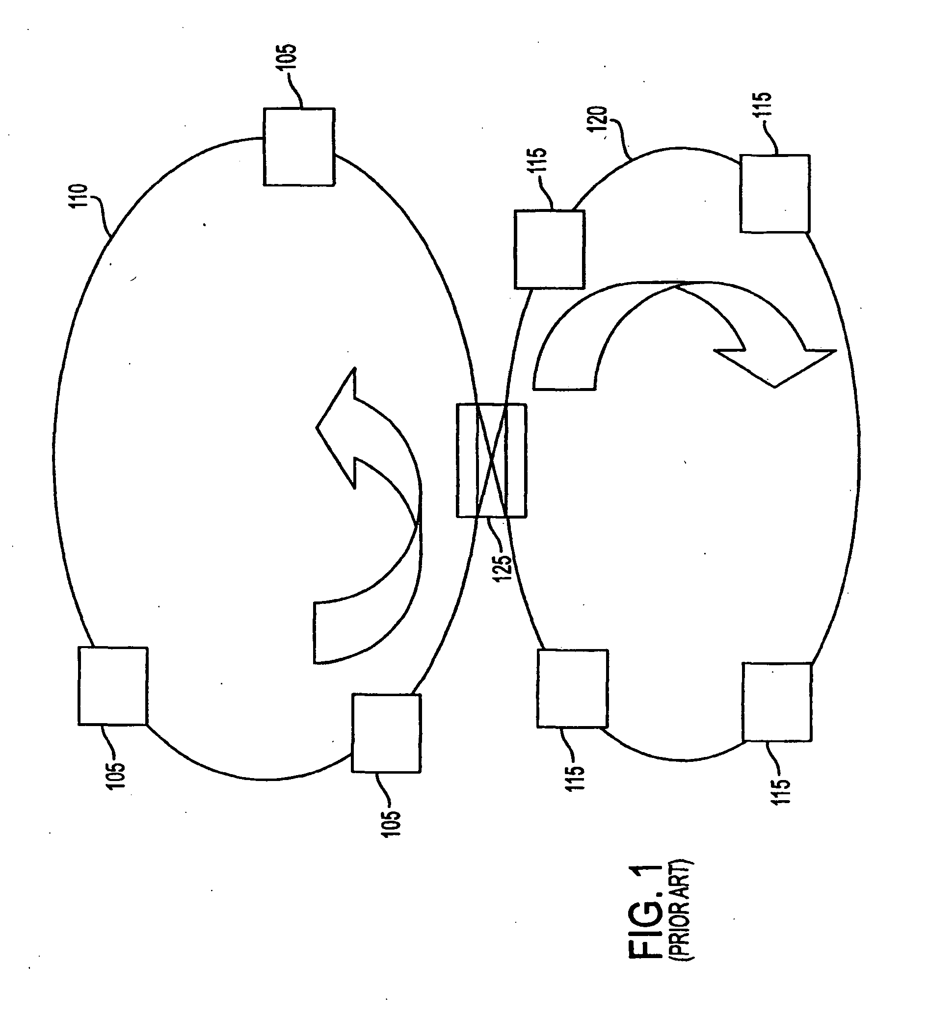
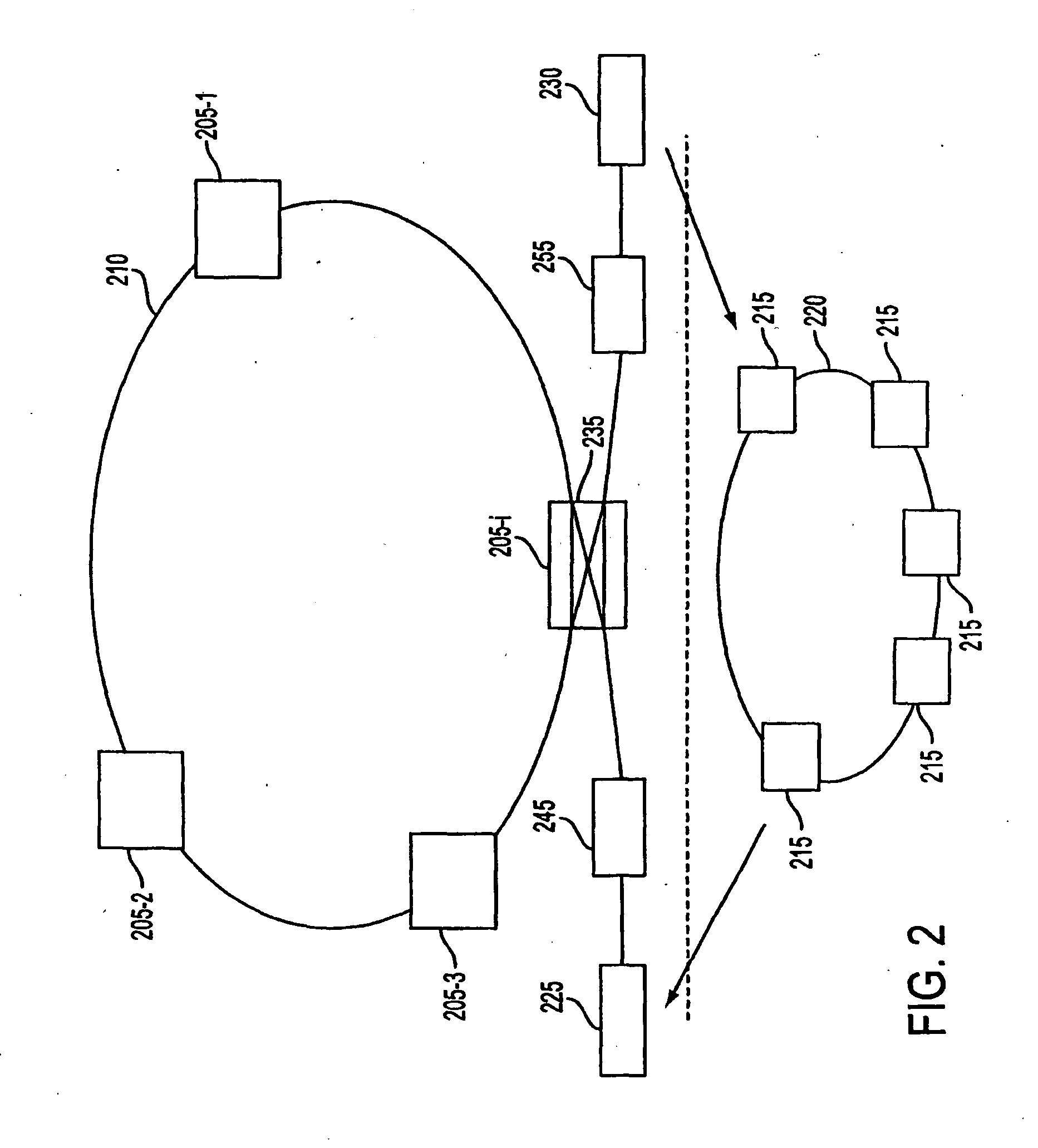
[0053]FIG. 2 is a diagram of the present invention from the perspective of the prior art proposed in FIG. 1. In the present invention the core optical ring 210 has a plurality of nodes 205-1, . . . 205-i with each node having a switch 235, which in the example in FIG. 2 is a 2×2 switch but which may be an n×n switch. There is a tunable laser 225, which generates packets locally and a receiver 230. Stacker 245 stacks the packets (at different wavelengths) generated by tunable laser 225 to form a composite packet in a single photonic time slot. Stacker 245 may be serial or parallel. Unstacker 255 unstacks or demultiplexes the packets locally. Unstacker 255 may be serial or parallel. The subtending system 220 also may have a plurality of nodes 215. A node comprises a switch, a transmitter (e.g. tunable laser), a stacker, an unstacker and a receiver (detector). The subtending system may or may not have an optical feed and may be a ring, a star, a bus or any other conventional distributi...


PUM


Abstract

A system for providing high connectivity communications over a composite packet-switched optical ring network comprises a plurality of nodes, each node further comprising, an optical crossbar switch connected to the packet-switched optical ring network, a rapidly tunable laser for serially generating a plurality of packets, each packet being generated at a different wavelength and a wavelength stacker for stacking the plurality of serially generated packets to form a composite packet.

Description

[0001] This application claims the benefit of priority of U.S. Provisional Application No. 60 / 240,464 filed Oct. 13, 2000 entitled “Composite Packet-Switching over WDM by Transparent Photonic Slot Routing”. This application further claims the benefit of priority of U.S. Provisional Application No. 60 / 239,766 filed Oct. 12, 2000 entitled “High-Capacity Packet-Switched Ring Network”.FIELD OF THE INVENTION [0002] The present invention relates generally to optical communications systems and in particular to composite packet-switching over WDM using transparent slot routing. The photonic slot routing ring networks use a novel packet stacking technique to add or drop packets, which are simultaneously time and wavelength division multiplexed. BACKGROUND OF THE INVENTION [0003] The capacity of WDM systems has been growing at a rate surpassing Moore's Law. Nevertheless, while telecommunication networks are evolving towards packet-switching, WDM systems still remain largely circuit-switched. ...

Claims


Application Information

Patent Timeline
IPC IPC(8): H04J14/00
CPCH04Q11/0066H04Q2011/0033H04Q2011/0075H04Q2011/0092
Inventor BORODITSKY, MIKHAILFRIGO, NICHOLAS J.
Owner BORODITSKY MIKHAIL
Learn More