
Fixation system for an implantable medical device

a medical device and fixation system technology, applied in the field of fixation system for implantable medical devices, can solve the problems of insufficient strength of suture or dacron ties, inability to derive suitable benefits from conventional hearing aid systems, and difficulty in drilling holes into surrounding bon

Active Publication Date: 2006-06-01
COCHLEAR LIMITED
View PDF50 Cites 100 Cited by
  • Summary
  • Abstract
  • Description
  • Claims
  • Application Information

AI Technical Summary

Benefits of technology

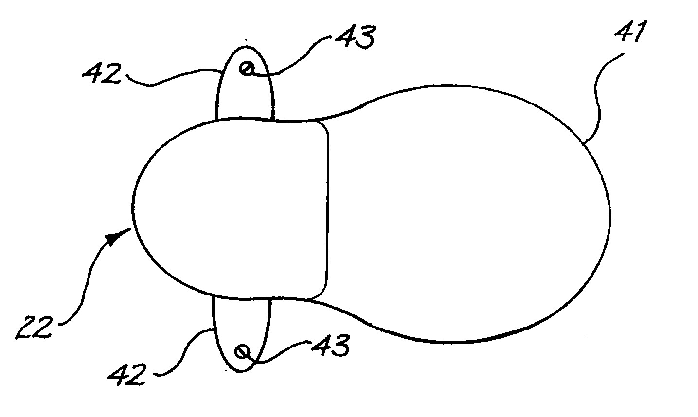
[0033] As defined above, the flanges are preferably securable to the surface of the tissue within the recipient. In one embodiment, one or more of the flanges can have orifices passing therethrough. These orifices can be adapted to receive tissue fixation devices, such as screws, clips and / or nails, including bone screws, bone clips and bone nails. In one embodiment, the screws can be countersunk, or have a round head. Still further, the tissue fixation devices can be resorbable.
[0039] The present invention provides a housing of an implantable component having one or more flanges for use in securing the component to a tissue surface of the recipient. In addition to supporting the component, the flanges have the additional characteristic of serving to protect the component from inadvertent dislodgment following an impact that might otherwise dislodge the component if positioned and mounted using conventional techniques.

Problems solved by technology

These people are unable to derive suitable benefit from conventional hearing aid systems, no matter how loud the acoustic stimulus is made, because there is damage to or absence of the mechanism for nerve impulses to be generated from sound in the normal manner.
One problem with this approach is that drilling of the holes into the surrounding bone can be a difficult and time consuming procedure, and especially for young children, much care must be taken by the surgeon to ensure that the drilling does not perforate the dura mater, as the skull thickness in such cases can be quite thin.
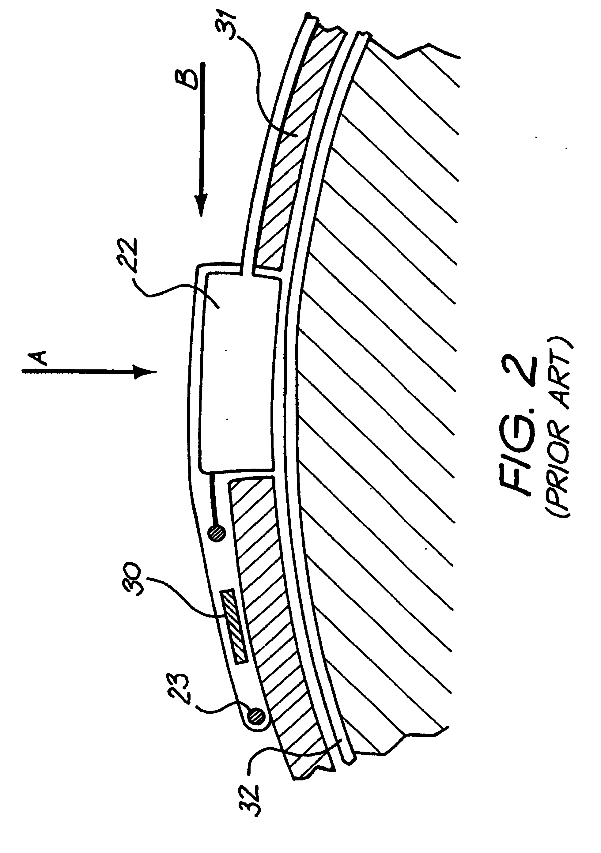
Further to this, the suture or Dacron ties may not be sufficiently strong enough to withstand a substantial impact to a region of the head adjacent the device and as a result, such a force may dislodge the device from its desired position.
In addition, it has been found that if a suture or Dacron tie is inadvertently placed across an inappropriate section of the device, such as across a strain relief of the electrode lead, the suture / tie may cause the lead / device to undergo fatigue and cause failure at this location.
This technique is not always possible depending upon the thickness of the surrounding bone and the age and anatomy of the recipient.

Method used


Image

  • Fixation system for an implantable medical device
  • Fixation system for an implantable medical device
  • Fixation system for an implantable medical device

Examples


Embodiment Construction

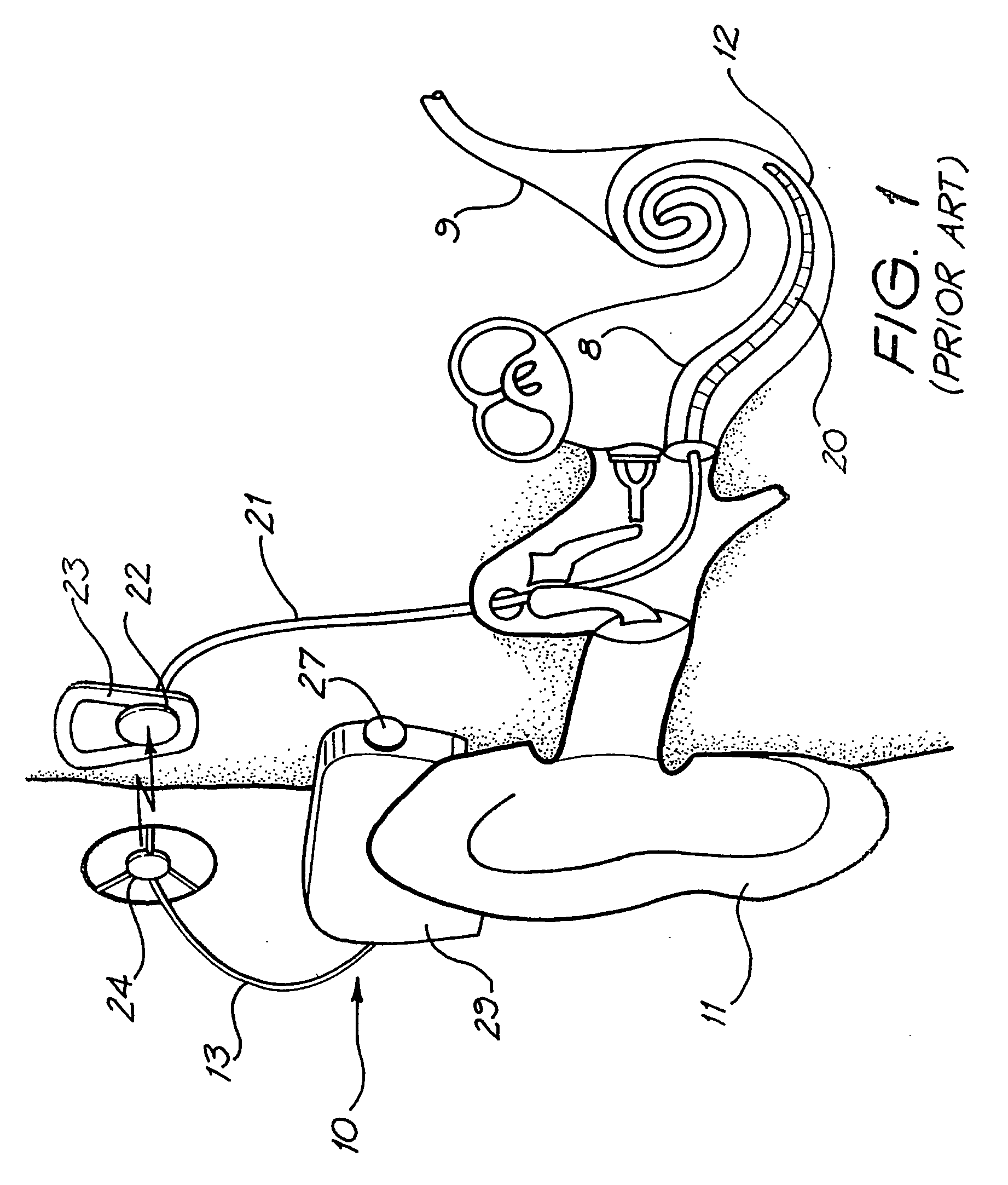
[0057] Before describing the features of the present invention, it is appropriate to briefly describe the construction of one type of known cochlear implant system with reference to FIG. 1.

[0058] Known cochlear implants typically consist of two main components, an external component including a speech processor 29, and an internal component including an implanted receiver and stimulator unit 22. The external component includes a microphone 27. The speech processor 29 is, in this illustration, constructed and arranged so that it can fit behind the outer ear 11 and is held in place behind the outer ear 11 via an ear-hook arrangement. Alternative versions may be worn on the body. Attached to the speech processor 29 via a cable 13 is a transmitter antenna coil 24 that transmits electrical signals to the implanted unit 22 via a radio frequency (RF) link.

[0059] The implanted component includes a receiver antenna coil 23 for receiving power and data from the transmitter coil 24. A cable ...


PUM


Abstract

A medical implant, such as an implantable component (22) of a tissue-stimulating prosthesis. One example of such a prosthesis being a cochlear implant. The component (22) is adapted to be implanted at or adjacent a tissue surface within the recipient, such as a bone surface. The component (22) has a housing and at least one flange (42) extending outwardly therefrom. The flange (42) can be secured to the tissue surface via a tissue fixation device, such as a bone screw (43).

Description

FIELD OF THE INVENTION [0001] The present invention resides in an improved method of mounting an implantable component of an implantable medial device, such as a cochlear implant package, securely in the head region of a recipient. BACKGROUND OF THE INVENTION [0002] In many people who are profoundly deaf, the reason for deafness is absence of, or destruction of, the hair cells in the cochlea which transduce acoustic signals into nerve impulses. These people are unable to derive suitable benefit from conventional hearing aid systems, no matter how loud the acoustic stimulus is made, because there is damage to or absence of the mechanism for nerve impulses to be generated from sound in the normal manner. [0003] It is for this purpose that cochlear implant systems have been developed. Such systems bypass the hair cells in the cochlea and directly deliver electrical stimulation to the auditory nerve fibres, thereby allowing the brain to perceive a hearing sensation resembling the natura...

Claims


Application Information

Patent Timeline
IPC IPC(8): A61N1/02A61F2/18A61F11/04A61N1/36
CPCA61F11/004A61F2220/0008A61N1/36032A61N1/375A61N1/37518A61F11/20A61N1/36036A61N1/36038A61N1/37223
Inventor GIBSON, PETERJOHANSEN, LARS VENDELBO
Owner COCHLEAR LIMITED
Learn More