
Spindle motor having hydrodynamic pressure bearing

a technology of hydrodynamic pressure and spindle motor, which is applied in the direction of sliding contact bearings, instruments, record information storage, etc., can solve the problems of increasing track density, noise and vibration, and burning or overheating of contacting portions, so as to achieve stable rotation and reduce vibration and noise of the motor.

Inactive Publication Date: 2006-06-01
SAMSUNG ELECTRO MECHANICS CO LTD
View PDF3 Cites 5 Cited by
  • Summary
  • Abstract
  • Description
  • Claims
  • Application Information

AI Technical Summary

Benefits of technology

[0021] Therefore, the present invention has been made in view of the above problems, and it is an object of the present invention to provide a spindle motor with a hydrodynamic pressure bearing for returning the sleeve slanted in a direction due to external shock to the vertical state using repulsive force caused by bearing load between components so that the spindle motor is stably rotated and stable reduction of vibration and noise of the motor can be secured.

Problems solved by technology

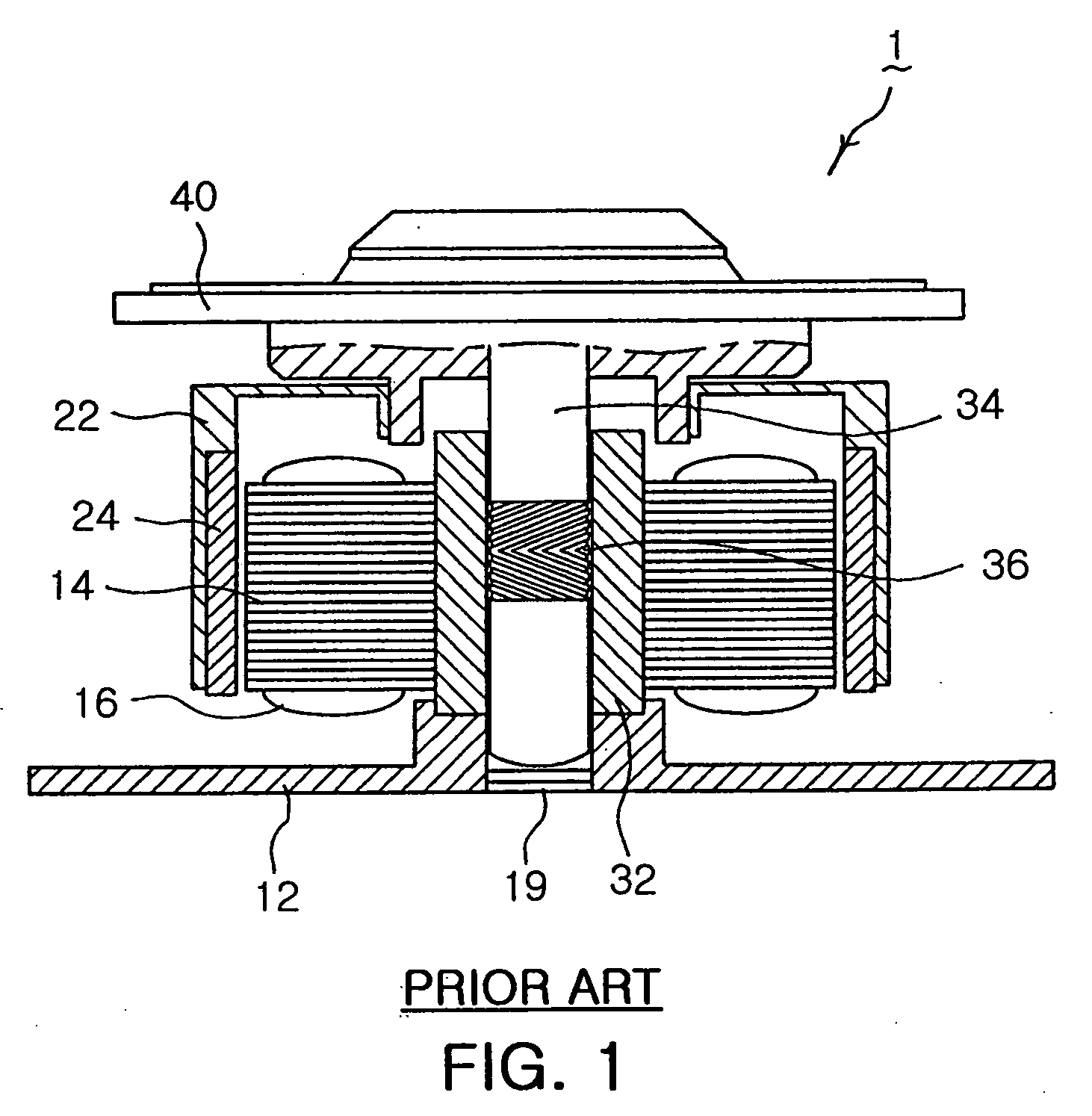
Generally, in a motor employing a ball bearing, friction is generated due to balls' rolling by the rotation of the bearings, and the friction causes noise and vibration.
The vibration is referred as to “Non Repeatable Run Out (NRRO)” and is one of the key obstacles to increasing the track density of hard disks.
Moreover, if abrasion due to the contact between the metal components is increased to generate high temperature at the contacting portion of the metal components, fusion that the contacting portions are burnt or overheated by the heat and the metal components stick or are welded to each other occurs.
In this case, since the inner circumference of the sleeve 32 and the outer circumference of the shaft 34 must be precisely fabricated according to the minimal dimensional gap, it is difficult to fabricate the components and costs for the fabrication are excessive so that costs for manufacturing the spindle motor are increased.

Method used


Image

  • Spindle motor having hydrodynamic pressure bearing
  • Spindle motor having hydrodynamic pressure bearing
  • Spindle motor having hydrodynamic pressure bearing

Examples


Embodiment Construction

[0055] Hereinafter, the present invention will be described in detail with reference to the accompanying drawings as follows.

[0056]FIG. 3 is a view illustrating an appearance of a shaft employed in a spindle motor having a hydrodynamic pressure bearing according to a first embodiment of the present invention, FIG. 4 is a sectional view of the spindle motor having a hydrodynamic pressure bearing according to the first embodiment of the present invention, and FIGS. 5a, 5b, and 5c illustrate the rotation of the spindle motor having a hydrodynamic pressure bearing according to the first embodiment of the present invention.

[0057] The spindle motor 100, as shown in FIGS. 3 to 5, converts the line-contact between metal components due to an external impact into the surface-contact between the metal components so as to return the metal components slanted by an external impact to the vertical state, and includes a stator 110, a rotor 120, a hydrodynamic pressure generator 130, and a surface...


PUM


Abstract

A spindle motor with a hydrodynamic pressure bearing is disclosed. The spindle motor with a hydrodynamic pressure bearing includes a stator having coils for generating electromagnetic force when electric power is applied to generate rotational driving force, a rotor rotated with respect to the stator and having magnets facing the winding coils, a hydrodynamic pressure generator having a shaft fixed to one of the stator and the rotor and a sleeve spaced apart from the shaft to face the shaft, at least one hydrodynamic pressure generating groove formed in one of the shaft and the sleeve, and at least one bearing load generator generating bearing load when the sleeve contacts the shaft and formed in one of the shaft and the sleeve. The spindle motor optimizes the shape of the sleeve and the shaft such that the spindle motor is stably rotated and vibration and noise can be reduced accordingly.

Description

RELATED APPLICATION [0001] The present invention is based on, and claims priority from, Korean Application Number 2004-98904, filed Nov. 29, 2004, the disclosure of which is incorporated by reference herein in its entirety BACKGROUND OF THE INVENTION [0002] 1. Field of the Invention [0003] The present invention relates to a spindle motor with a hydrodynamic pressure bearing, and more particularly to a spindle motor with a hydrodynamic pressure bearing for optimizing the shapes of a sleeve and a shaft such that the sleeve, when deviated to one side due to external shock, is returned to the vertical state using repulsive force caused by bearing load between components so that a motor is stably rotated and stable reduction of vibration and noise of the motor can be secured. [0004] 2. Description of the Related Art [0005] Generally, in a motor employing a ball bearing, friction is generated due to balls' rolling by the rotation of the bearings, and the friction causes noise and vibratio...

Claims


Application Information

Patent Timeline
Patent Type & Authority Applications(United States)
IPC IPC(8): F16C32/06
CPCF16C17/026F16C17/105F16C33/107H02K7/085F16C2370/12G11B19/20
Inventor LEE, HO
Owner SAMSUNG ELECTRO MECHANICS CO LTD
Learn More