Optical disk apparatus
a technology of optical disk and writing film, which is applied in the field of information writing devices, can solve the problems of frequent buffer-underrun condition, delay of heat on the writing film, and inability to correct errors, so as to reduce the probability of substantial impossibility of correction
- Summary
- Abstract
- Description
- Claims
- Application Information
AI Technical Summary
Benefits of technology
Problems solved by technology
Method used
Image

Examples
first embodiment
[0038] The first exemplary embodiment of the present invention is demonstrated hereinafter with reference to the accompanying drawings.
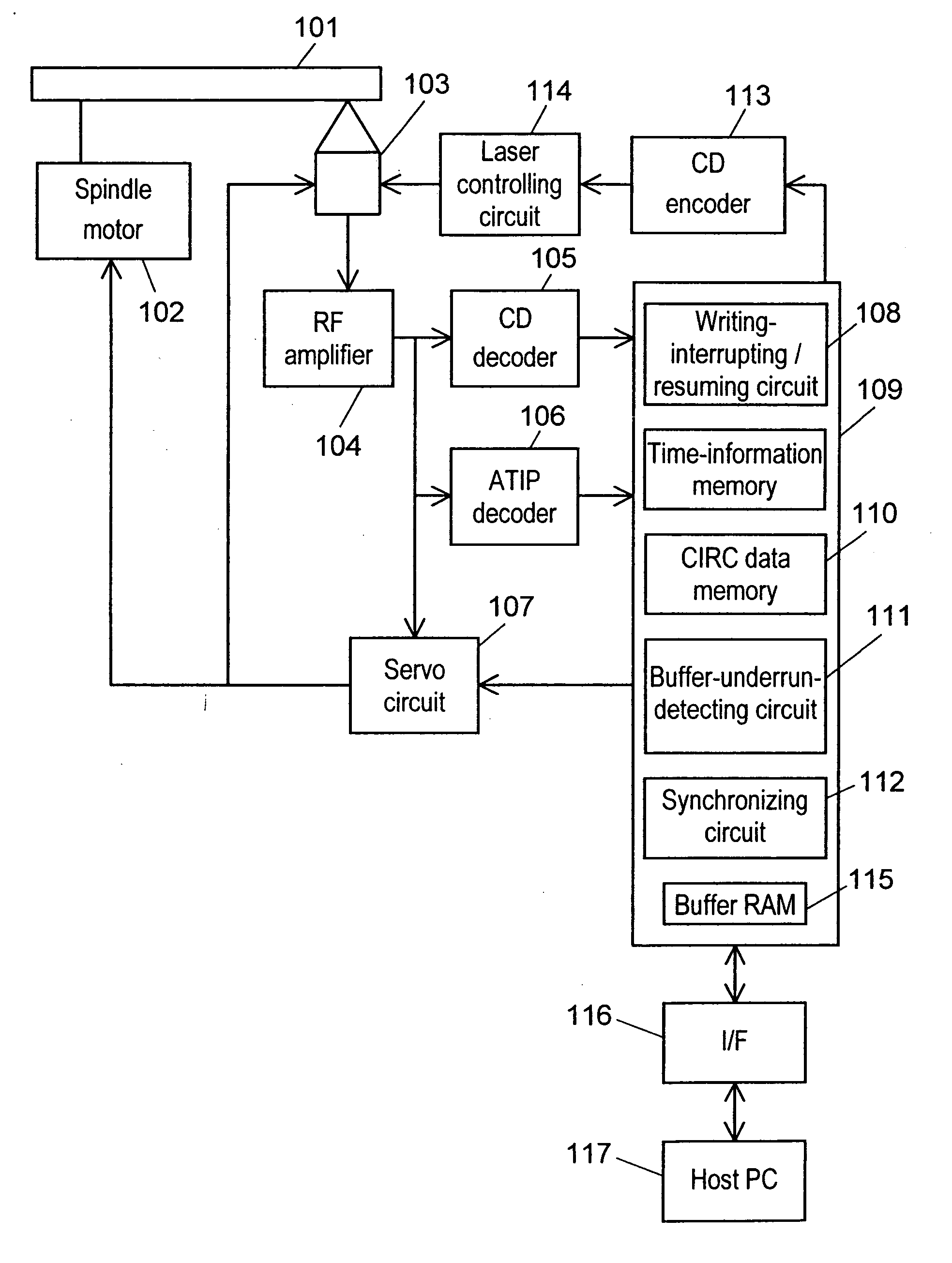
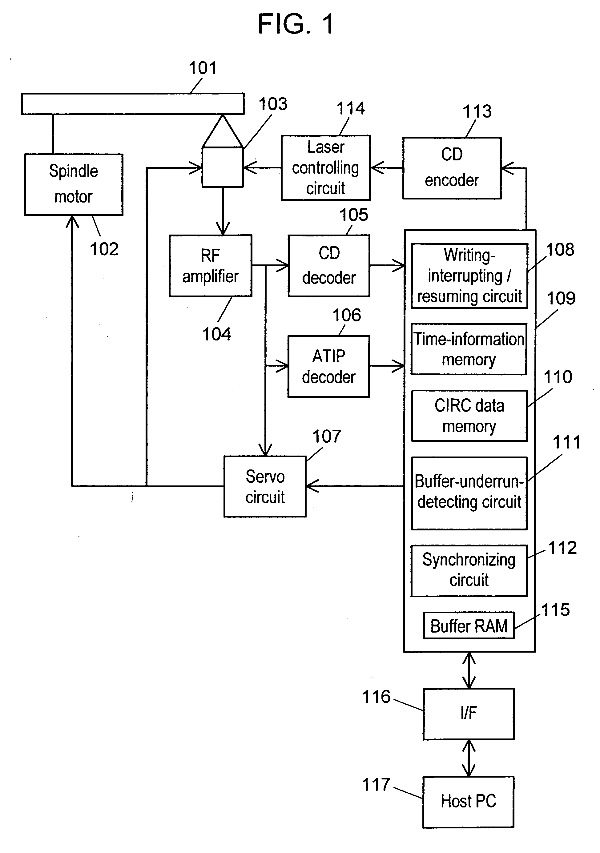
[0039]FIG. 1 shows a block diagram explaining a structure of an optical disk apparatus of the present invention. Components are explained hereinafter with reference to FIG. 1.
[0040] Optical disk 101 is an information-writing medium such as CD-R, CD-RW, DVD-R or DVD-RW, on which data are written, and includes a writable information-writing layer. A CD-Recordable (CD-R) and a CD-Rewritable (CD-RW) based on the CD standards are described hereinafter, where the CD-R is referred to as a recordable optical disk and the CD-RW is referred to as a rewritable optical disk.
[0041] Spindle motor 102 is a rotating-driving means for driving and rotating optical disk 101. Optical pick-up 103 irradiates laser beam on a writing surface of optical disk 101, thereby writes data on optical disk 101, or optical pick-up 103 detects reflected light, thereby reproduces th...
second embodiment
[0073] A structure of an optical disk apparatus of the second embodiment is the same as that in FIG. 1. FIG. 4 shows a chart explaining an interrupted and resumed position of writing of the optical disk apparatus in accordance with the second embodiment of the present invention. Writing data synchronized with a reference clock signal are arrayed by CD encoder 113. Writing data 301 for writing on optical disk 101 is shown in FIG. 4. Frame 302 is a writing-data row formed of 588 channel bits. Frame 302 is a minimum unit, and a writing data is generally formed of a plurality of frame 302.
[0074] Frame-sync signal 303 is disposed at the head of frame 302, and used for synchronizing the data for writing and the reference clock signal in the optical disk apparatus in a reading process.
[0075] In FIG. 4, writing data 304 is a data written on optical disk 101 or a data written after interrupting and resuming of writing. Writing-interrupting position 305 of frame n is a position for interrup...
third embodiment
[0100] An operation (interrupting and resuming of writing on optical disk 101) of an optical disk apparatus in accordance with the third embodiment of this invention is explained hereinafter.
[0101]FIG. 7 shows a flowchart explaining interrupting and resuming of writing of the optical disk apparatus in accordance with the third embodiment of the present invention.
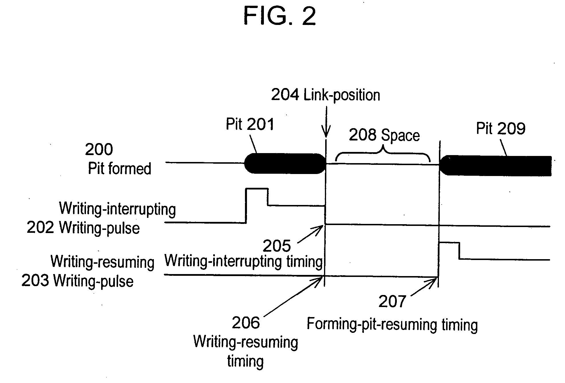
[0102] The third exemplary embodiment is demonstrated hereinafter with reference to FIGS. 1, 2, 4, and 7. In FIGS. 1, 2, 4, and 7, interrupting of writing on optical disk 101 is executed within an area from the last position of one frame to a position of the maximum possible number for correcting, which the optical disk has, and at link-position 204 after forming continuous pit 201.
[0103] In step 41, when an amount of data in buffer RAM 115 is not more than a given amount of data, buffer-underrun-detecting circuit 111 detects the buffer-underrun condition, and informs a buffer-underrun condition to writing-interrupting-an...
PUM
 Abstract
Description
Claims
Application Information
 - R&D
- Intellectual Property
- Life Sciences
- Materials
- Tech Scout
- Unparalleled Data Quality
- Higher Quality Content
- 60% Fewer Hallucinations
Browse by: Latest US Patents, China's latest patents, Technical Efficacy Thesaurus, Application Domain, Technology Topic, Popular Technical Reports.
© 2025 PatSnap. All rights reserved.Legal|Privacy policy|Modern Slavery Act Transparency Statement|Sitemap|About US| Contact US: help@patsnap.com