
Imaging device

a technology of image pickup and spherical mirror, which is applied in the direction of optical elements, television systems, instruments, etc., can solve the problems of dead angle at which the camera is unable to take a picture, the inability to combine images with high, and the difficulty of handling the pyramidal mirror

Inactive Publication Date: 2006-06-01
SONY CORP
View PDF4 Cites 18 Cited by
  • Summary
  • Abstract
  • Description
  • Claims
  • Application Information

AI Technical Summary

Benefits of technology

The present invention relates to an image pickup apparatus with multiple image pickup units. The image pickup units are located in a way that their image pickup areas overlap each other. The apparatus satisfies a conditional equation that ensures that the viewpoint centers of the image pickup units lie within a sphere with a diameter of 20 mm. This allows for the overlap of images from different image pickup units without causing parallax. The image pickup units are also located in a way that the angle of view from the image pickup device to the lens is larger than the angle of view of another image pickup unit, which makes it possible for the viewpoint centers of the image pickup units to be substantially coincident with each other. The technical effect of this invention is to provide an image pickup apparatus with multiple image pickup units that can capture images without causing parallax and with a wide view angle.

Problems solved by technology

However, according to this arrangement, since viewpoints centers of the respective cameras are not coincident with each other, parallax (parallax) is produced between the cameras so that a plurality of images cannot be joined with high quality.
Also, when it is intended to take a picture of an object near (within the shortest range) the camera, it is unavoidable that the dead angle at which the camera is unable to take a picture is produced.
However, since the above-mentioned arrangement needs the pyramidal mirror, problems arise, in which the whole of an image pickup apparatus becomes large in size and in which the mirror should be prevented from being cracked or smudged so that it is difficult to handle the pyramidal mirror.
Further, since it is not possible to take a picture in the direction along the central axis of the pyramid (in the upper and lower direction in the ordinary location of the pyramidal mirror) due to the structure of the pyramidal mirror, it is difficult to take pictures in all directions.

Method used


Image

  • Imaging device
  • Imaging device
  • Imaging device

Examples


Embodiment Construction

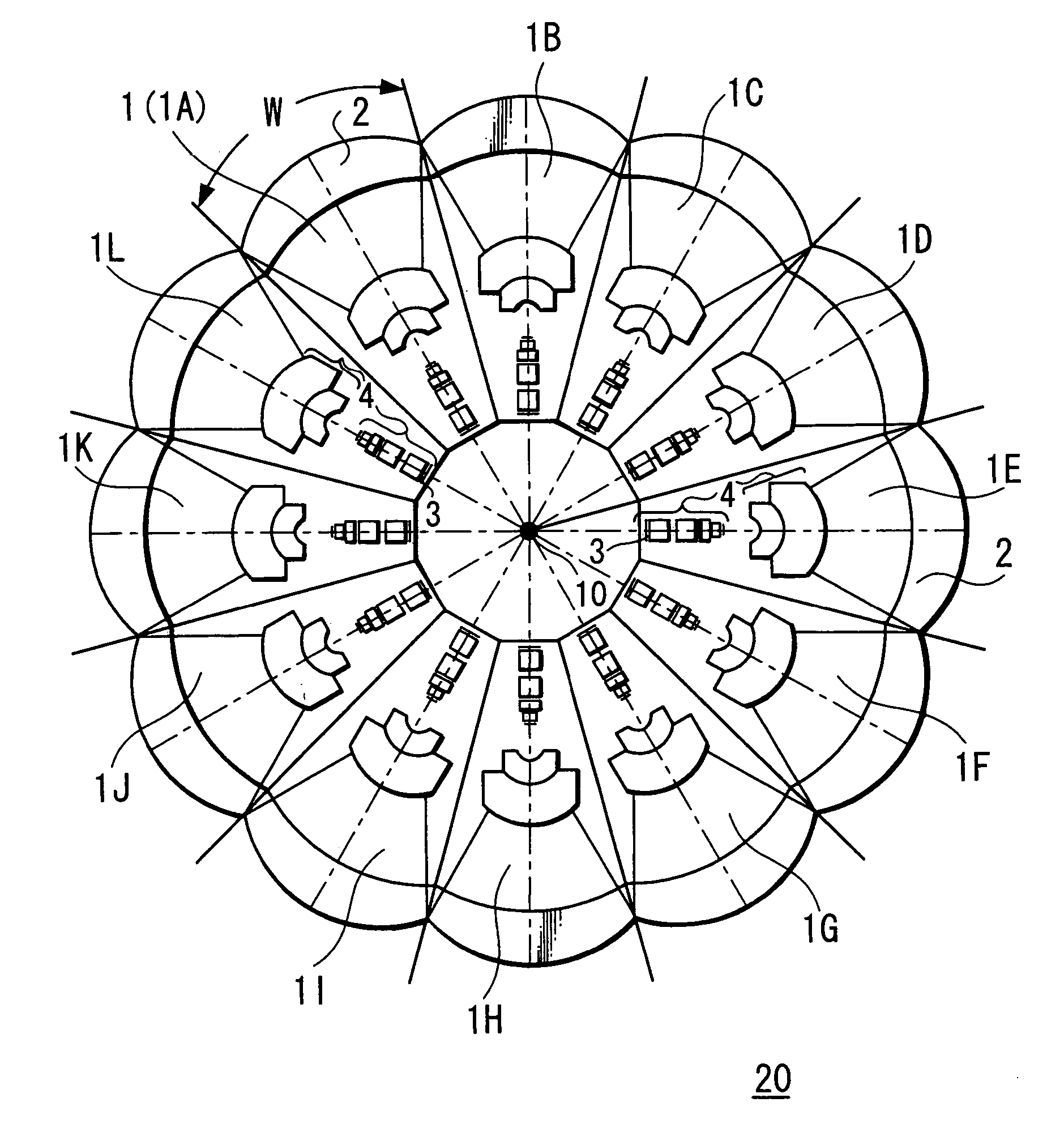
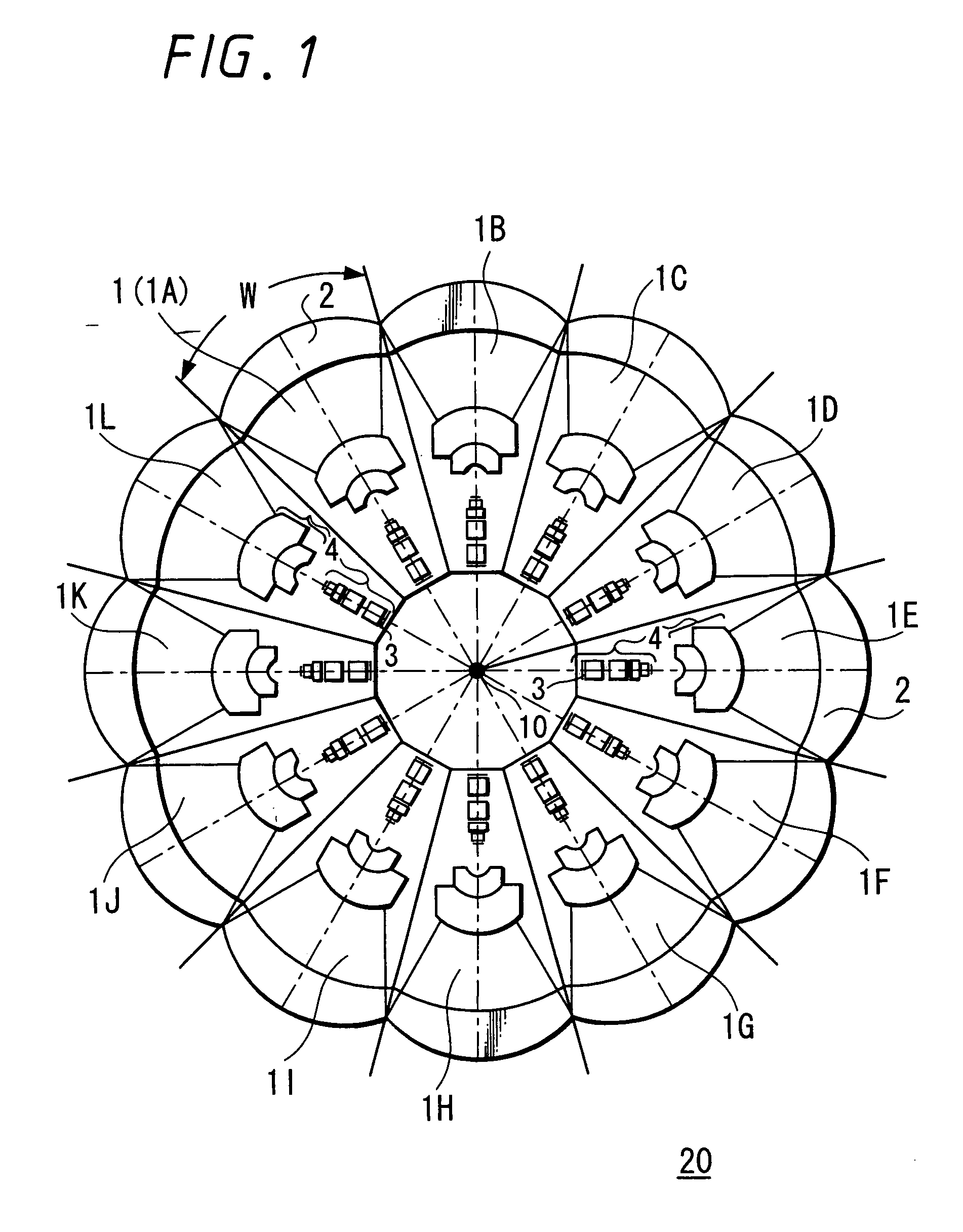
[0024]FIG. 1 is a schematic construction diagram (cross-sectional view along the horizontal direction) showing an image pickup apparatus according to an embodiment of the present invention.

[0025] This image pickup apparatus 20 is constructed in such a manner that 12 (1A, 1B, 1C, 1D, 1E, 1F, 1G, 1H, 1I, 1J, 1K, 1L) image pickup units (cameras) 1 including a front lens 2 and an image pickup device 3 are located in a radial fashion and that the adjacent image pickup units 1 are joined together.

[0026] In each image pickup unit 1, the front lens 2 is located at its front end and the image pickup device 3 is located near its rear end. Each image pickup unit includes a lens group 4 between the front lens 2 and the image pickup device 3.

[0027] According to this arrangement, the respective image pickup units 1A to 1L share image pickup areas of 30 degrees each to provide an image pickup area of 360 degrees in total.

[0028] In order that images obtained from the adjacent image pickup units...


PUM


Abstract

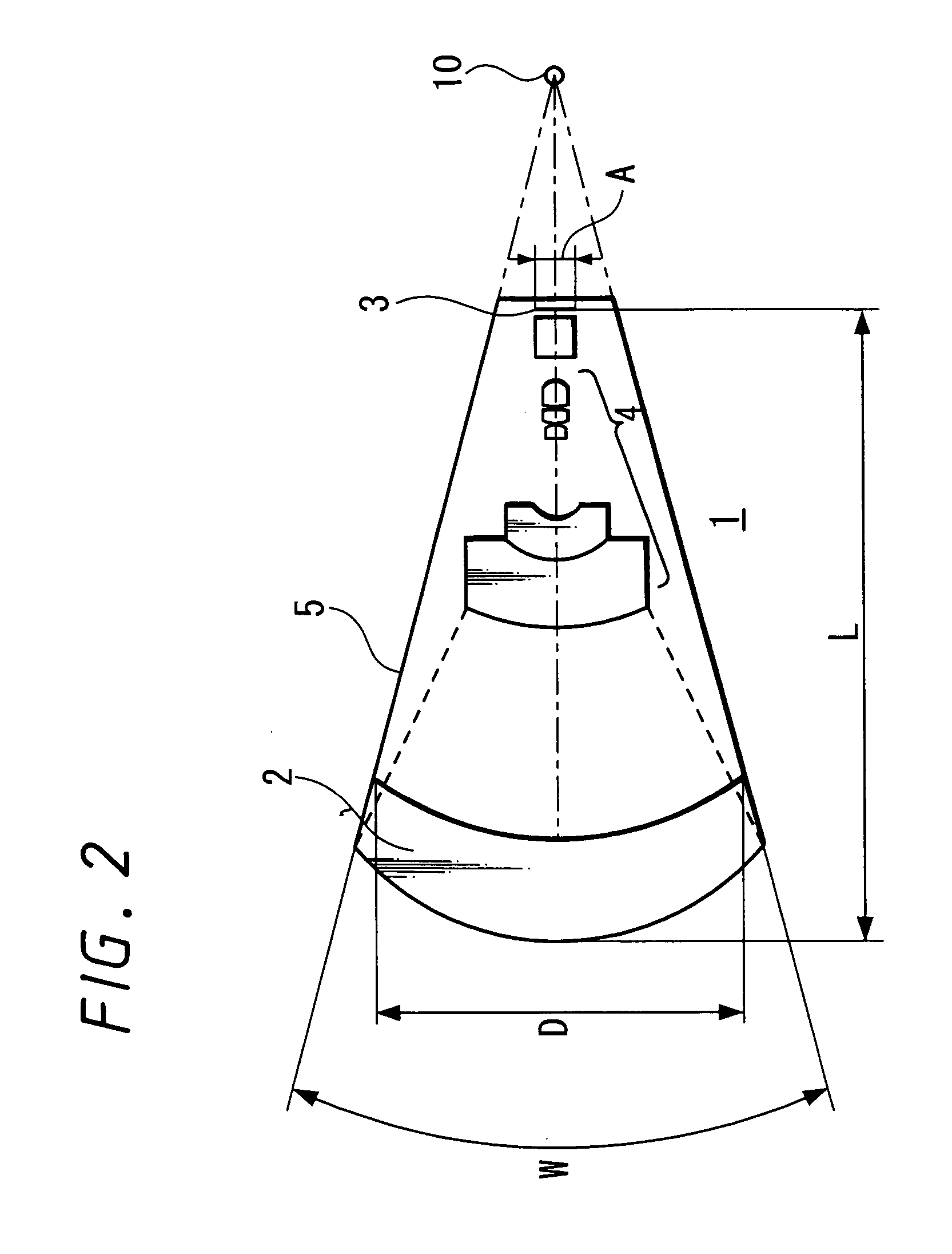
An image pickup apparatus is able to shoot an image of a wide range by a plurality of image pickup units, it is able to obtain excellent image quality and it can be miniaturized. An image pickup apparatus 20 comprises a plurality of image pickup units 1 including an image pickup device 3 and a front lens 2, the adjacent image pickup units 1 being located in such a manner that image pickup areas overlap each other and the image pickup units being located so as to satisfy a conditional equation AL<fD (1) where a cross-section passing a viewpoint center, an image pickup device 3 and a front lens 2 is created in the direction in which the image areas of the adjacent image pickup portions overlap with each other, a cross-section length of the image pickup device 3 is assumed to be A, a cross-section length of the front lens 2 is assumed to be D, a length from the front lens 2 to the image pickup device 3 is assumed to be L and a focal length which results from synthesizing the whole of the lenses within the image pickup unit 1 containing the front lens 2 is assumed to be f and that the viewpoint center of each image pickup unit 1 may lie within a sphere with a diameter of 20 mm.

Description

TECHNICAL FIELD [0001] The present invention relates to an image pickup apparatus composed of a plurality of image pickup units including a lens and an image pickup device. BACKGROUND ART [0002] A large number of image pickup apparatus capable of shooting a picture of a wide angle of view by using a plurality of cameras have been proposed so far. [0003] For example, there has been proposed an image pickup apparatus in which a plurality of cameras is mounted on a polyhedron frame (see cited patent reference 1, for example). [0004] However, according to this arrangement, since viewpoints centers of the respective cameras are not coincident with each other, parallax (parallax) is produced between the cameras so that a plurality of images cannot be joined with high quality. Also, when it is intended to take a picture of an object near (within the shortest range) the camera, it is unavoidable that the dead angle at which the camera is unable to take a picture is produced. [0005] On the o...

Claims


Application Information

Patent Timeline
Patent Type & Authority Applications(United States)
IPC IPC(8): H04N5/225G02B13/06G03B15/00G03B37/04
CPCG02B13/06G03B15/00G03B37/04H04N5/2254H04N23/698H04N23/00H04N13/243
Inventor YOSHIKAWA, KOICHI
Owner SONY CORP
Learn More