
Tiltsensor

a tilt sensor and tilt technology, applied in the field of high-, can solve the problems of over-exceeding the measuring range, affecting the accuracy of measurement results, and the effort involved in the adjustment of the installation of a single tilt sensor, and achieving the effect of high resolution and precision

Inactive Publication Date: 2006-05-25
UNIV OF BREMEN
View PDF7 Cites 6 Cited by
  • Summary
  • Abstract
  • Description
  • Claims
  • Application Information

AI Technical Summary

Benefits of technology

[0016] According to a further embodiment of the invention, the first electronic circuit is provided for selecting the electrode configuration within which the gas bubble is located or which configuration is closest to the gas bubble. Here the second electronic circuit is provided for determining the location of the gas bubble within the electrode configuration selected by the first circuit. This makes it possible to achieve the high-resolution determination of the location of the gas bubble by evaluating only the electric output quantities of a single (the selected) electrode configuration.
[0028] According to a further embodiment of the invention, the spirit level with the electrode configurations can also extend over an angle of ±30-40°. The preferred areas of application for this embodiment are locations that are particularly difficult to access, such as the sea floor. Tiltsensors having such a large tilt angle measuring range can be installed without costly adjustments and operated for a long period of time.

Problems solved by technology

The effort involved in adjustment for the installation of a single tiltsensor, which is typically meant to provide measurement results for a period of months or even years, is relatively minor.
Adjustment expenses become significant at the latest when, in the course of long-term measurements, it becomes apparent that the measuring range will be exceeded and that a readjustment of the tiltsensor will become necessary.
Readjustment generally makes measurements difficult and costly.
95062 USA features these characteristics, but fails to provide the desired, enlarged tilt angle measuring range.

Method used


Image

  • Tiltsensor
  • Tiltsensor
  • Tiltsensor

Examples


Embodiment Construction

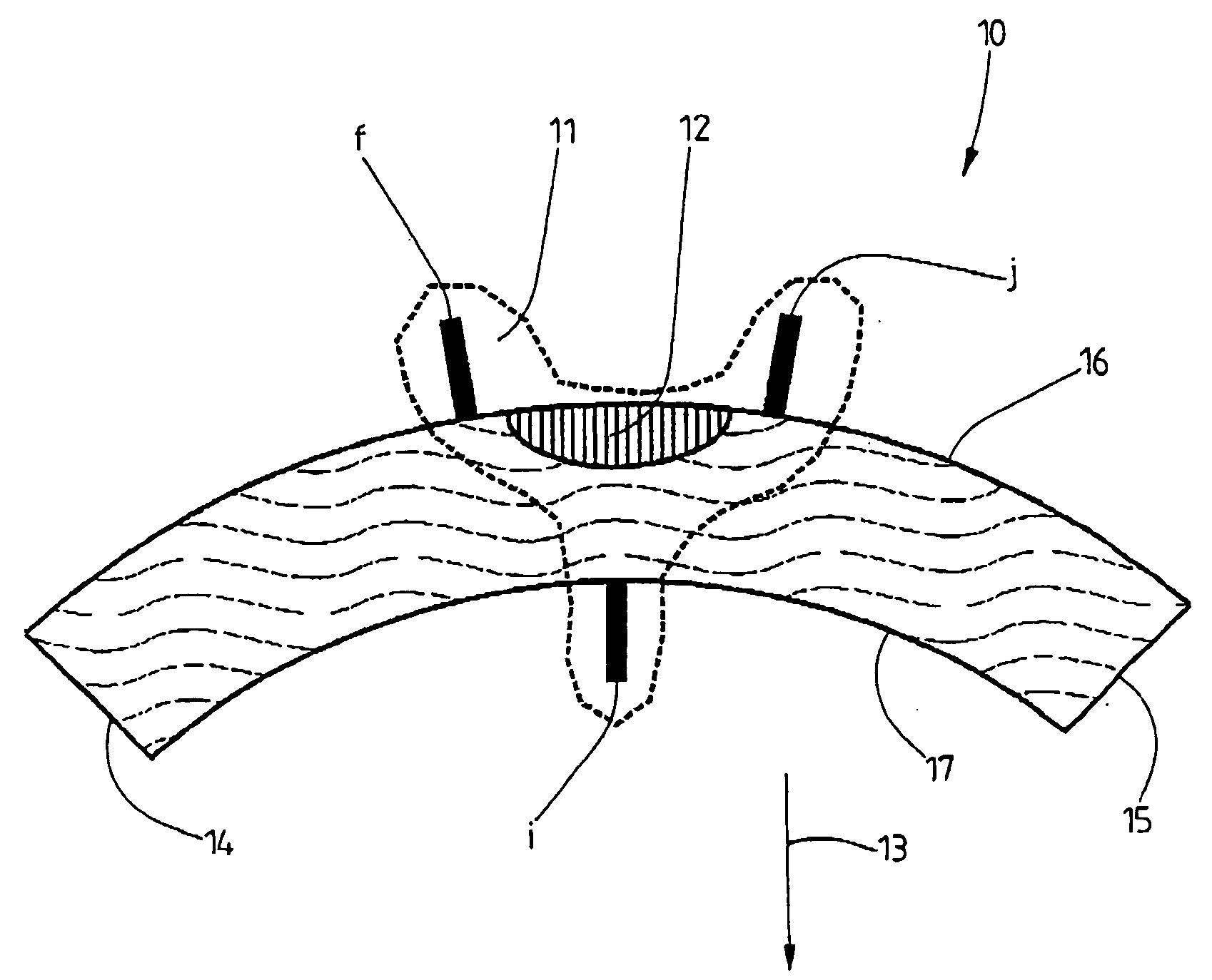
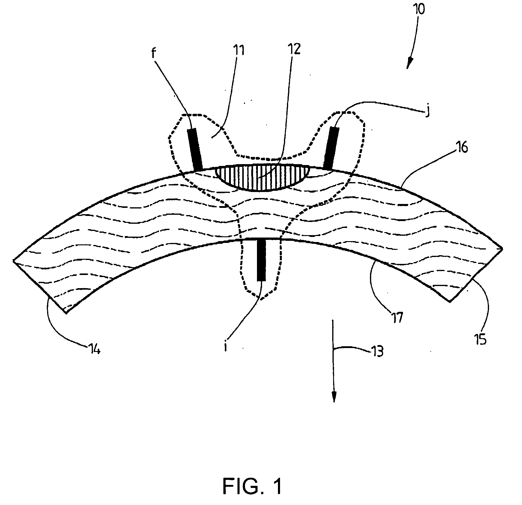
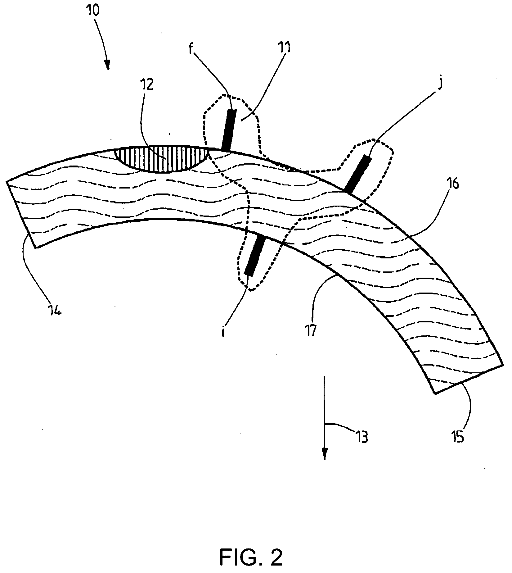
[0041] A conventional tiltsensor employing a spirit level 10 has one electrode configuration 11 comprising three electrodes f, i and j. The spirit level 10 is curved to correspond to an arc of a circle and is filled with an electrolytic liquid. The spirit level 10 also contains a small gas bubble 12 whose liquid buoyancy causes it to migrate to the highest position of the spirit level 10 and maintain its position there. In the drawing according to FIG. 1, the spirit level 10 is aligned with respect to the plumb direction (arrow 13) such that the gas bubble 12 maintains approximately the same distance to each end 14, 15 of the spirit level. This plumb-adjusted sensor position corresponds to its initial position after installation for monitoring movements of objects.

[0042] As a result of its curved shape, the spirit level 10 has a top, outer side 16 and an opposite bottom, inner side 17. Arranged on the outer side 16 are the two electrodes f and j, which are spaced apart from each ot...


PUM


Abstract

An adjustment-free tiltsensor for application in the fields of geodesy, geophysics and geotechnics, with a tilt angle measuring range greater than ±5° to ±10° and an essentially enhanced angular resolution better than 1 microradiant, in which an electrolytic liquid and a gas bubble are present in a closed spirit level, the spirit level is curved over an angle of up to 360°, a plurality of electrode configurations each having a plurality of electrodes are arranged along the spirit level for sensing the position of the gas bubble, the electrodes are in electric contact with the electrolytic liquid, and the electrodes are connected to a first electronic circuit, by means of which the electric quantities between selected electrodes can be measured.

Description

BACKGROUND OF THE INVENTION [0001] 1. Field of the Invention [0002] The invention relates to a high-resolution, preferably adjustment-free tiltsensor and a method for determining the tilt angle of the tiltsensor. [0003] 2. Description of the Related Art [0004] The use of high-resolution tiltsensors is known in the fields of geodesy, geophysics and geotechnics. A resolution of one microradiant or better is required in order to measure tiniest movements of objects. This high resolution is achieved by specially designed methods and sophisticated circuitry, but also by accepting a small measuring range of the tilt angle. The latter usually lies at approximately ±1°. These tiltsensors have a curved spirit level that contains an electrically conducting (electrolytic) liquid as well as a small gas bubble. The position of the gas bubble varies according to the tilt of the spirit level and is scanned by three electrodes. Such a high-resolution constructive design is shown in the User's Manua...

Claims


Application Information

Patent Timeline
IPC IPC(8): G01C9/06
CPCG01C9/06G01C9/34G01C2009/068
Inventor FABIAN, MARCUS
Owner UNIV OF BREMEN
Learn More