
Utility monitoring system and method for relaying personalized real-time utility consumption information to a consumer

a monitoring system and utility technology, applied in the field of electric devices, can solve the problems of increasing utility costs, reducing overall energy demand, and reducing utility costs, and achieve the effect of facilitating demand-side management suppor

Inactive Publication Date: 2006-05-18
SAN VISION ENERGY TECH
View PDF2 Cites 267 Cited by
  • Summary
  • Abstract
  • Description
  • Claims
  • Application Information

AI Technical Summary

Benefits of technology

[0016] Yet a further object of the present invention is to provide a new and improved utility monitoring system and method that facilitates Demand-Side Management support based on real-time utility consumption and cost information, as well as peak cost and aggregate consumption data.

Problems solved by technology

Presently, we live in an era of electricity blackouts and escalating utility costs due to the growing divergence between the increasing power demand and the decreasing generation capabilities.
Encouraging awareness of consumption patterns not only reduces the overall energy demand, but also results in consumers saving significant money on their monthly energy bill.
However, most consumers are unaware of the rate and cost of their utility consumption.
The problem for most consumers is that their home utility meter, which measures their utility consumption, is in an obscure place, such as in their basement or outside their home.
Furthermore, the utility meters only provide the quantity of the utility being consumed.
By that time it is too late for the consumers to take any actions that would curb their utility consumption.
Consumers that are aware of their utility consumption may still find it difficult to gauge whether their utility consumption should be reduced because they have no point of reference as to what would constitute an appropriate level of consumption.
Calculating whether the current utility consumption will exceed that of a previous month can be quite difficult and tedious.
Most consumers would undoubtedly not examine their previous bills to determine appropriate utility consumption levels.
Most consumers, however, do not have the time or the desire to research the conservation information.
However, until now, DSM has not used peak cost, aggregate consumption, or forecasted consumption and cost of consumption values as the factors for determining when to reduce the utility consumption.
Furthermore, DSM has not been able to make customized adjustments to individual locations based on data taken from those locations.

Method used


Image

  • Utility monitoring system and method for relaying personalized real-time utility consumption information to a consumer
  • Utility monitoring system and method for relaying personalized real-time utility consumption information to a consumer
  • Utility monitoring system and method for relaying personalized real-time utility consumption information to a consumer

Examples


Embodiment Construction

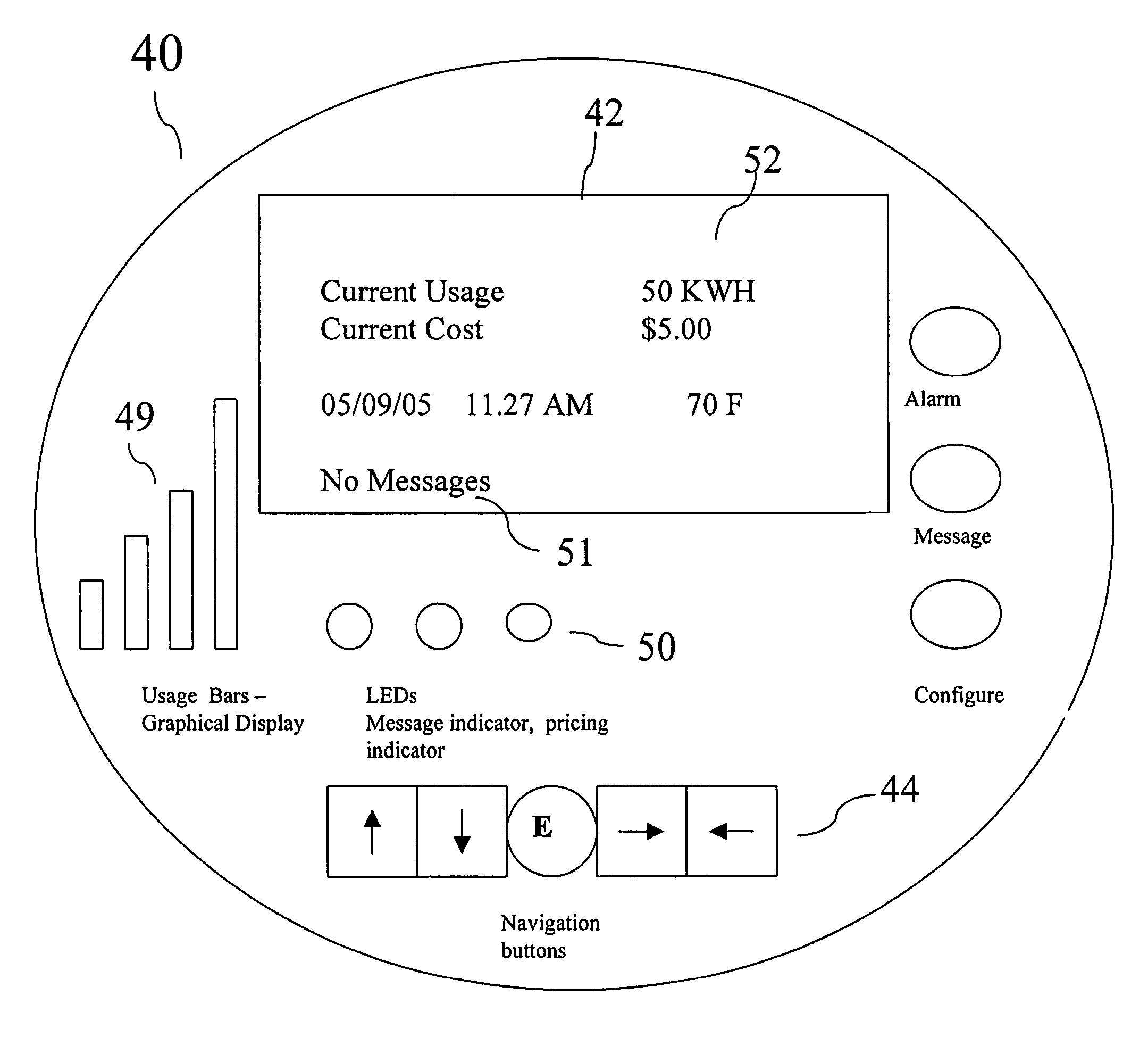
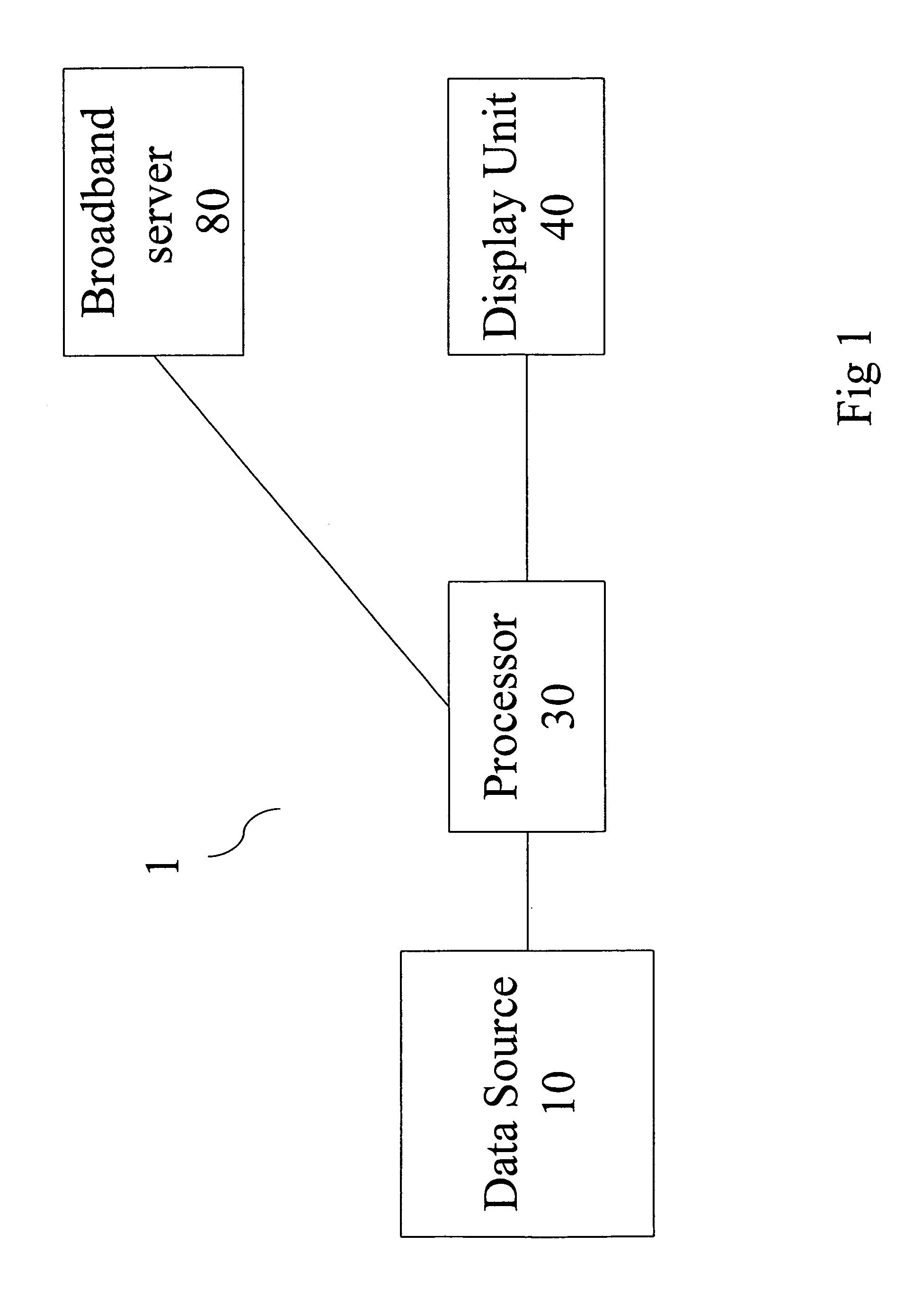
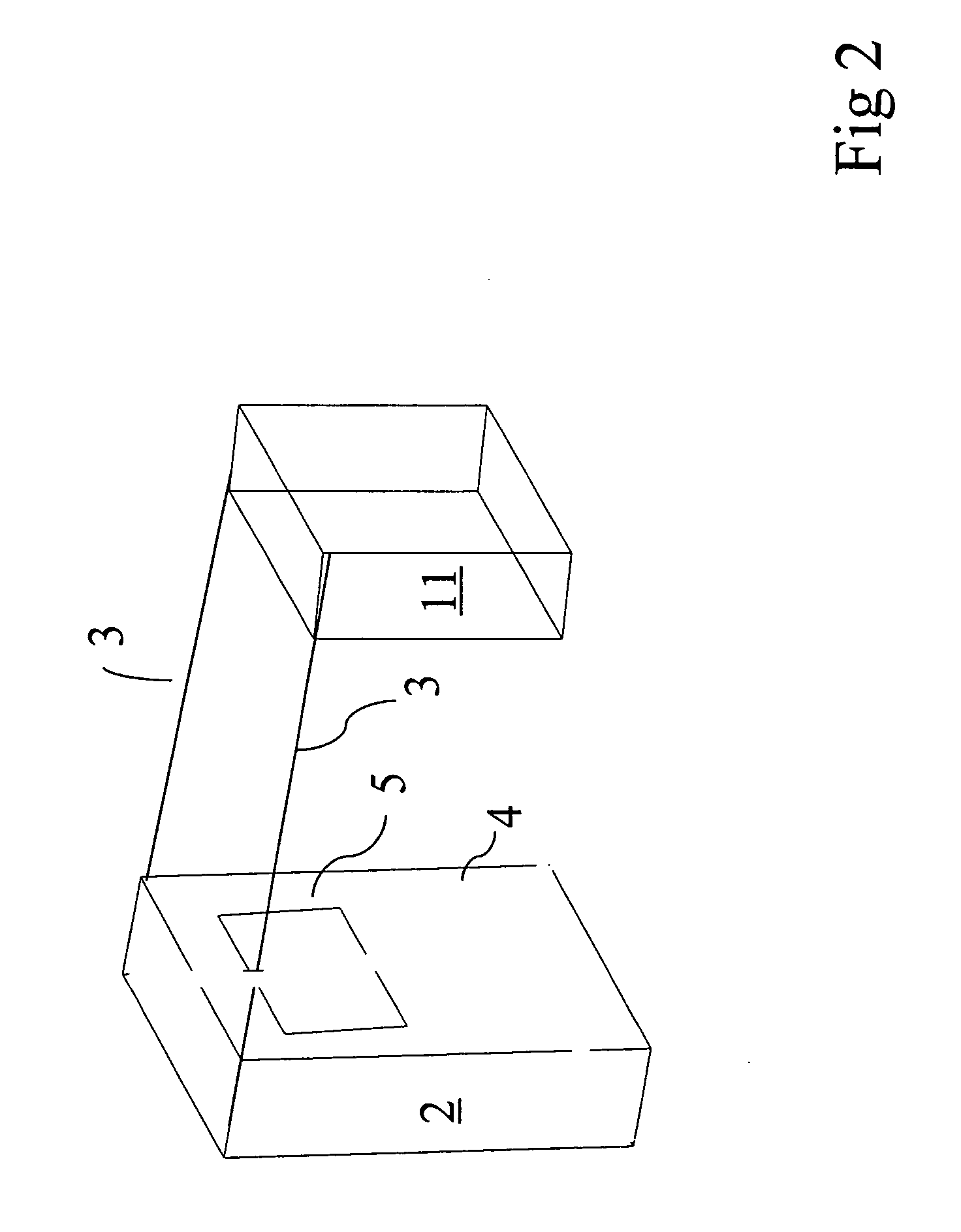
[0037] The invention will now be described with reference to FIGS. 1 to 5, which in general disclose a preferred embodiment of a new and improved utility monitoring system and method for relaying to a consumer personalized utility consumption information. In the figures, like reference characters designate identical or corresponding parts or steps throughout the several views. It is understood that the figures represent only a preferred embodiment of the invention.

[0038] Referring now to FIG. 1, a utility monitoring system for relaying to a consumer personalized real-time utility consumption information in accordance with the present invention is identified generally by reference numeral 1. The utility monitoring system 1 includes a data source 10, a processor 30 coupled to the data source 10, and a display unit 40 coupled to the processor 30. The utility monitoring system 1 may also include a broadband server 80 coupled to either the processor 30 or the display unit 40. It is unde...


PUM


Abstract

A utility monitoring system and method for relaying to a consumer personalized utility consumption information in order to induce the consumer to conserve the utility. The system includes a data source, a processor coupled to the data source, and a display unit coupled to the processor. The processor receives utility consumption information from the data source. The processor then generates enhanced utility consumption information, as well as a display of the data. The processor may also provide Demand-Side Management for utility conservation based on the utility consumption information and the consumer's settings. The display is then transmitted to the display unit to be displayed. The display unit resides in the consumer's home or business. A broadband server may also be used to provide customized broadband information.

Description

[0001] This patent application claims the benefit of U.S. provisional patent application 60 / 628,904, filed Nov. 17, 2004.FIELD OF THE INVENTION [0002] The present invention generally relates to electronic devices, and in particular, to utility (i.e. electricity, gas and water) monitoring systems and methods for relaying personalized utility consumption information to a consumer. BACKGROUND OF THE INVENTION [0003] Presently, we live in an era of electricity blackouts and escalating utility costs due to the growing divergence between the increasing power demand and the decreasing generation capabilities. A number of initiatives have surfaced to counter this dilemma. The proposed solutions include searching for alternative energy sources, higher efficiency energy devices, and energy conservation methods. [0004] An effective method of utility conservation is reducing consumer consumption by changing a consumer's utility consumption practices. For example, a consumer may turn off lights ...

Claims


Application Information

Patent Timeline
Patent Type & Authority Applications(United States)
IPC IPC(8): G01R21/133G01R11/56
CPCG01D4/002G01R21/1333G06Q50/06Y04S20/46Y02B90/241Y04S20/32G01D2204/18Y02B90/20Y04S20/30
Inventor JANARTHANAN, RAJALINGAM
Owner SAN VISION ENERGY TECH
Learn More