
Nonlinear inversion

a receiver filter and inversion technology, applied in the field ofsignal processing, can solve the problems of complex design of the receiver filter b>106/b>, the inability to and the inability to easily achieve the effect of conventional linear filters

Inactive Publication Date: 2006-05-18
AVAGO TECH WIRELESS IP SINGAPORE PTE
View PDF6 Cites 1 Cited by
  • Summary
  • Abstract
  • Description
  • Claims
  • Application Information

AI Technical Summary

Benefits of technology

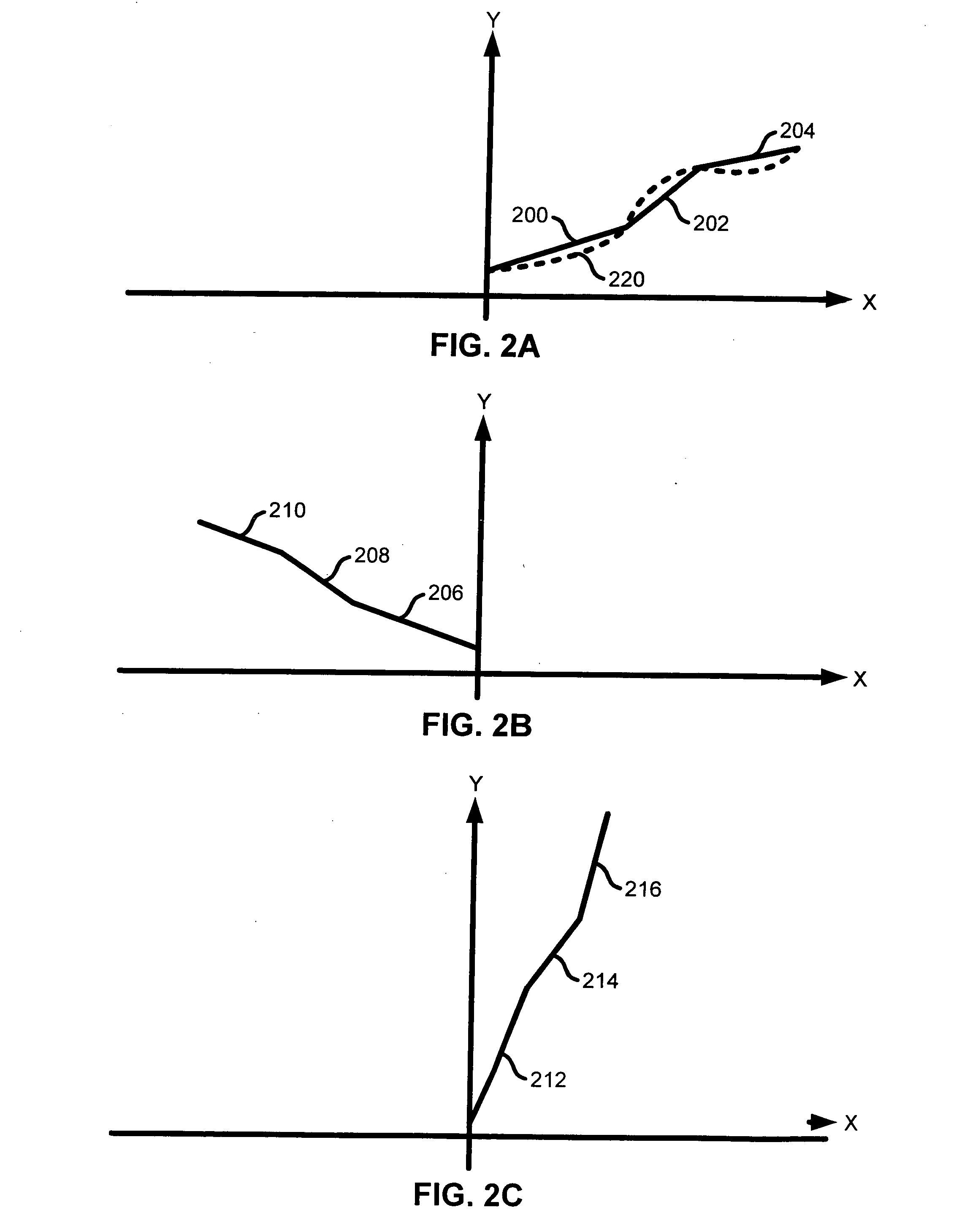
The approach enables the easy implementation of receiver filters for nonlinear channels, reducing signal degradation and distortion by using linearized transfer functions with first-order polynomials, improving noise characteristics and stability.

Problems solved by technology

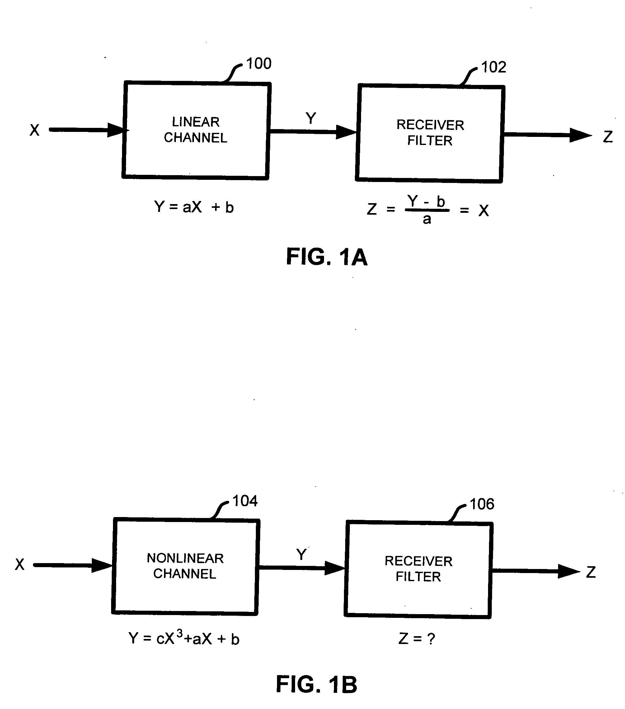
Thus, the design of receiver filter 106 becomes complex, and cannot be easily achieved using conventional linear filters.
Generally, the complexity of receiver filter design tends to increase for transfer functions that include higher order polynomials.
The challenges involved in inverting the transfer functions of nonlinear channels make it difficult to design receiver filters.
Signal degradation, distortion and instability are often results of suboptimal receiver filter design.

Method used


Image

  • Nonlinear inversion
  • Nonlinear inversion
  • Nonlinear inversion

Examples


Embodiment Construction

[0025] It should be appreciated that the present invention can be implemented in numerous ways, including as a process, an apparatus, a system, or a computer readable medium such as a computer readable storage medium or a computer network wherein program instructions are sent over optical or electronic communication links. It should be noted that the order of the steps of disclosed processes may be altered within the scope of the invention.

[0026] A detailed description of one or more preferred embodiments of the invention is provided below along with accompanying figures that illustrate by way of example the principles of the invention. While the invention is described in connection with such embodiments, it should be understood that the invention is not limited to any embodiment. On the contrary, the scope of the invention is limited only by the appended claims and the invention encompasses numerous alternatives, modifications and equivalents. For the purpose of example, numerous ...


PUM


Abstract

A system and method are disclosed for processing a signal propagated through a nonlinear channel. The method includes modeling the channel characteristics to produce a linearized channel model, deriving an inverse linearized channel model from the linearized channel model, and filtering the signal using the inverse linearized channel model.

Description

FIELD OF THE INVENTION [0001] The present invention relates generally to signal processing. More specifically, the processing of a signal propagated through a nonlinear channel is disclosed. BACKGROUND OF THE INVENTION [0002] In digital communication systems, a signal is often transmitted to a receiver via a channel that may be described using a transfer function. The receiver may implement a filter whose transfer function is substantially the inverse of the channel transfer function in order to undo the effect of channel and facilitate recovery of the signal. FIG. 1A is a block diagram illustrating a receiver filter used to receive a signal transmitted through a linear channel. In the block diagram, the signal is transmitted through a linear channel 100. The relationship between the output, Y, and the input, X, is expressed as a linear equation Y=aX+b   (Equation 1) [0003] where a and b are constant coefficients. The inverse of the linear equation, Z=Y-ba(Equation⁢ ⁢2)[0004] leads...

Claims


Application Information

Patent Timeline
Patent Type & Authority Applications(United States)
IPC IPC(8): H04B1/10H03H17/02H04L25/03
CPCH03H17/0261H03H17/0286H04L25/03006
Inventor BATRUNI, ROY G.
Owner AVAGO TECH WIRELESS IP SINGAPORE PTE
Learn More