
Customizable touch input module for an electronic device

a touch input module and electronic device technology, applied in the field of electronic input devices, can solve the problems of insufficient interaction, lack of functions, and inability to provide independent control, and achieve the effect of increasing the number of functions

Inactive Publication Date: 2006-05-18
ATRUA TECH
View PDF15 Cites 279 Cited by
  • Summary
  • Abstract
  • Description
  • Claims
  • Application Information

AI Technical Summary

Benefits of technology

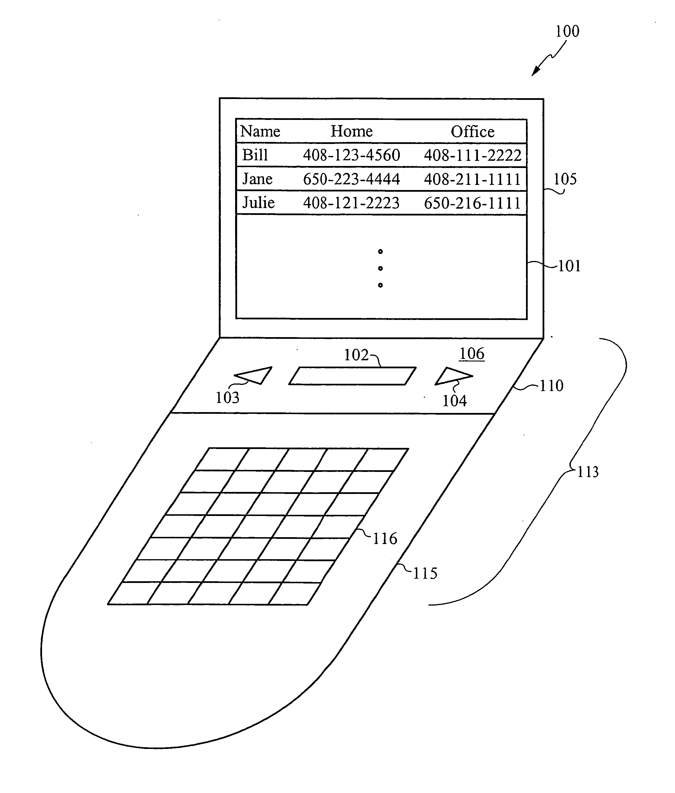
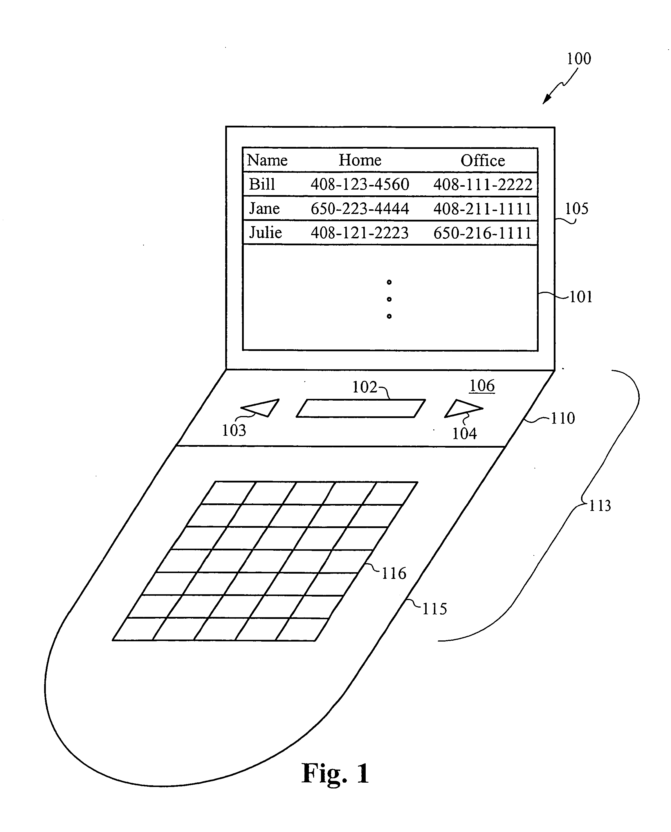
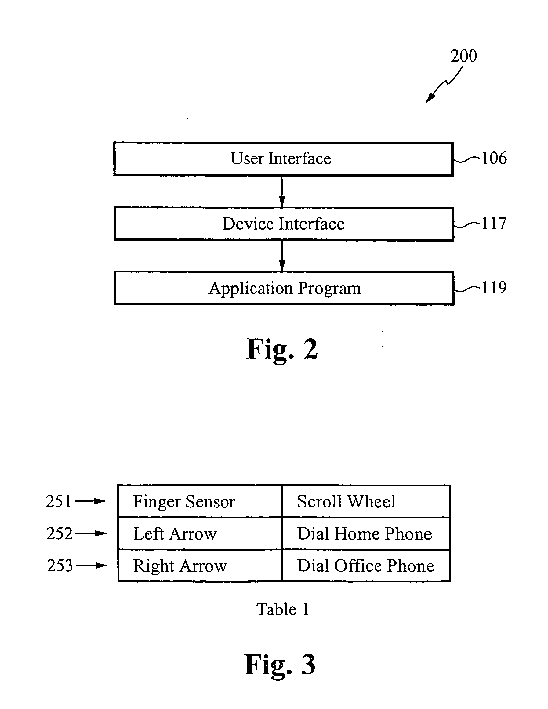
[0007] The present invention is directed to systems for and methods of customizing device interfaces. The device interfaces couple interface modules, which comprise a user interface having a finger sensor and mechanical components, to an underlying electronic device. In accordance with the present invention, any number of user interfaces are able to be selected, based on their look and function, and are coupled to an electronic device. A user thus has more options in selecting how to use an electronic device. Moreover, this customization allows a manufacturer to increase the number of functions that the electronic device, controlled using the user interface, can perform. For example, the user interface is able to be customized so that applications executing on the electronic device are able to recognize and differentiate between more combinations of inputs from the user interface.

Problems solved by technology

For example, finger sensors do not have the tactile feel that users of electronic devices, such as electronic games, enjoy.
The number of functions, along with the lack of interaction, provided by such independent controls is inadequate for many applications.
Systems that combine a finger sensor and a mechanical control also suffer because the outputs from the sensor and the mechanical control must be specifically tailored to the electronic device that incorporates them.
This need for unique, independent interfaces has many limitations in product design and application development resulting in a shortfall of overall appeal of multi-functional products to consumers.

Method used


Image

  • Customizable touch input module for an electronic device
  • Customizable touch input module for an electronic device
  • Customizable touch input module for an electronic device

Examples


Embodiment Construction

[0027] In accordance with the present invention, an electronic housing containing a user interface is able to be integrated with any number of electronic devices, such as a mobile telephone, a digital camera, a game device, and a game controller. Preferably, the user interface contains input components, including a finger sensor and one or more mechanical input components, such as a push button, a scroll wheel, a joy stick, a touch pad, a dial, and a pressure sensor. The user interface is configured to provide to a host system electronic signals, data, and control information corresponding to electronic signals, data, and control information generated by a user input device. Alternatively, the user interface also contains output components such as speakers, light emitting diode (LED) displays, and liquid crystal displays (LCDs). Using a method of the present invention, a user is able to select a housing to suit his particular needs, select an electronic device, and then have an inte...


PUM


Abstract

A system having a customized interface for providing user inputs to an electronic device and a method for configuring the system is disclosed. The system comprises a user interface that includes a finger sensor and a mechanical component, both for receiving user inputs. A customizable device interface couples the user interface to an electronic device, such as a mobile telephone or a digital camera. The device interface is configured to selectively map the output of the user interface to any number of programmed inputs used by the electronic device. Any combination of components that form the user interface can thus be selected and the device interface configured so that the outputs of the components are mapped to functions recognizable by application programs executing on the electronic device. In one embodiment, for example, the output of a finger sensor is used to control a mobile phone; in another embodiment the output of the finger sensor is used to control a digital camera.

Description

RELATED APPLICATIONS [0001] This application claims priority under 35 U.S.C. § 119(e) of the co-pending U.S. provisional application Ser. No. 60 / 629,169, filed on Nov. 17, 2004, and titled “INTELLIGENT TOUCH INPUT MODULE.” The provisional application Ser. No. 60 / 629,169, filed on Nov. 17, 2004, and titled “INTELLGENT TOUCH INPUT MODULE,” is hereby incorporated by reference.FIELD OF THE INVENTION [0002] The present invention relates to electronic input devices. More particularly, the present invention relates to systems for and methods of customizing fingerprint sensors and mechanical controls to provide inputs to electronic devices. BACKGROUND OF THE INVENTION [0003] Finger sensors are now used on an ever increasing number of electronic devices. On some electronic devices, for example, finger sensors have replaced mechanical controls, such as buttons and knobs. The use of finger sensors to replace mechanical controls, however, has several drawbacks. For example, finger sensors do no...

Claims


Application Information

Patent Timeline
IPC IPC(8): G09G5/00H04M1/72403H04M1/72427
CPCG06F3/03547G06F2203/0338G06F2203/0339H04M1/274508H04M1/274525H04M1/72522H04M1/72544H04M2250/12H04M2250/22H04M1/2747H04M1/27453H04M1/72427H04M1/72403
Inventor GIOELI, ANTHONY
Owner ATRUA TECH
Learn More