
Networked movable barrier operator system

a technology of networked movable barriers and operator systems, which is applied in the direction of anti-theft devices, program control, instruments, etc., can solve the problems of insufficient in-depth diagnosis of this type of operator, the inability of known prior art operators to communicate their internal operating status to the outside world, and the inability of operators to respond to feedback

Inactive Publication Date: 2006-05-18
WAYNE DALTON CORP
View PDF21 Cites 67 Cited by
  • Summary
  • Abstract
  • Description
  • Claims
  • Application Information

AI Technical Summary

Problems solved by technology

Known prior art operators have limited capability of communicating their internal operating status to the outside world.
Furthermore, the feedback capacity of operators is very limited and in most cases it is only accessible at the time of the operator encountering a problem.
In-depth diagnosis of this type of operator is inadequate.
But, current or historical profile information is not easily accessible by the user or installer.
In addition to limited outbound communications with the outside world, prior art operators also have limited receive functions.
Although the wireless receiver system allows for more control command options such as in the case of multi-function wireless wall stations, the commands are still limited in scope and are only “local” (short range).
Although the aforementioned operators are effective in their stated purpose, they do not address the need to incorporate a movable barrier operator into a network system.

Method used


Image

  • Networked movable barrier operator system
  • Networked movable barrier operator system
  • Networked movable barrier operator system

Examples


Embodiment Construction

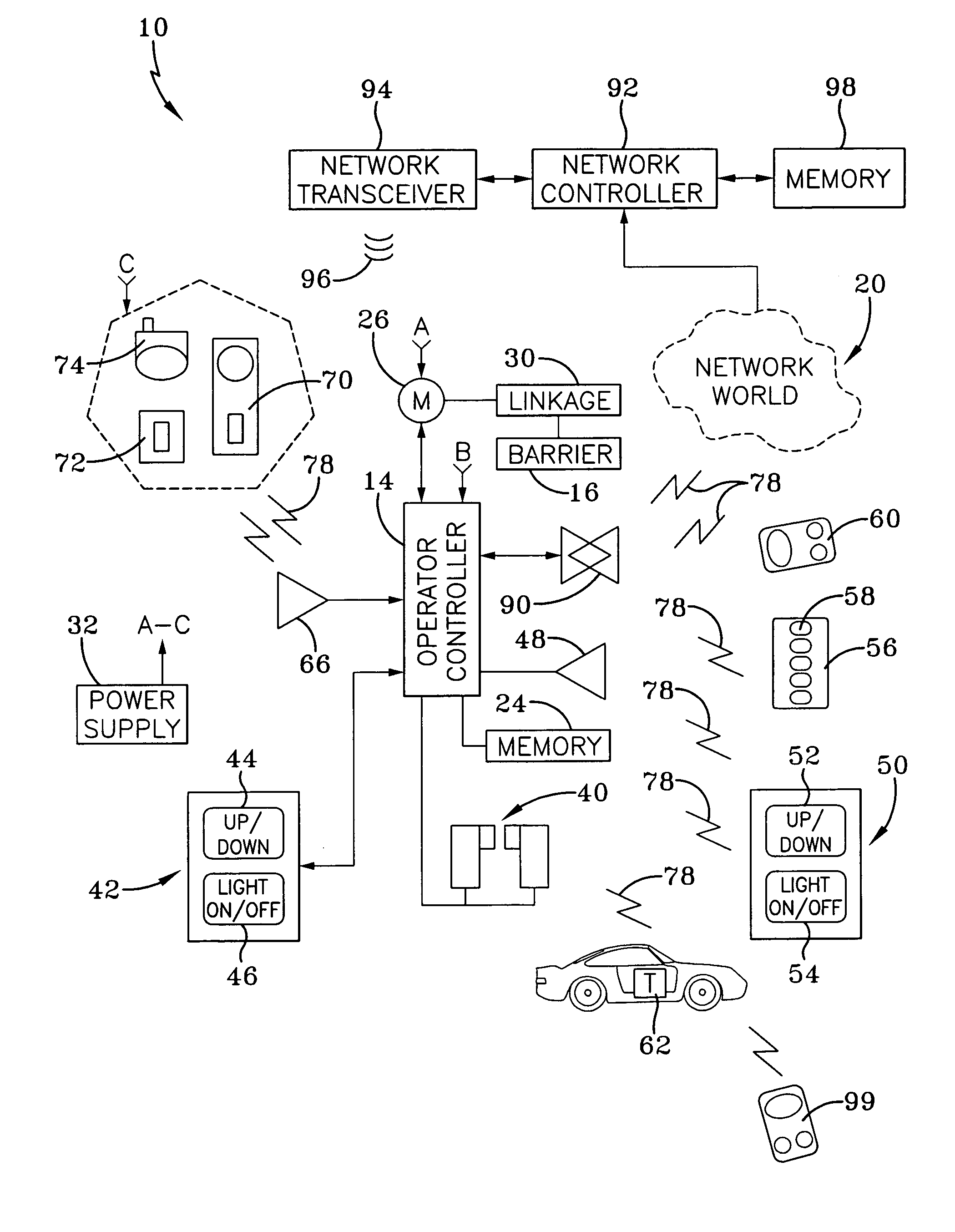
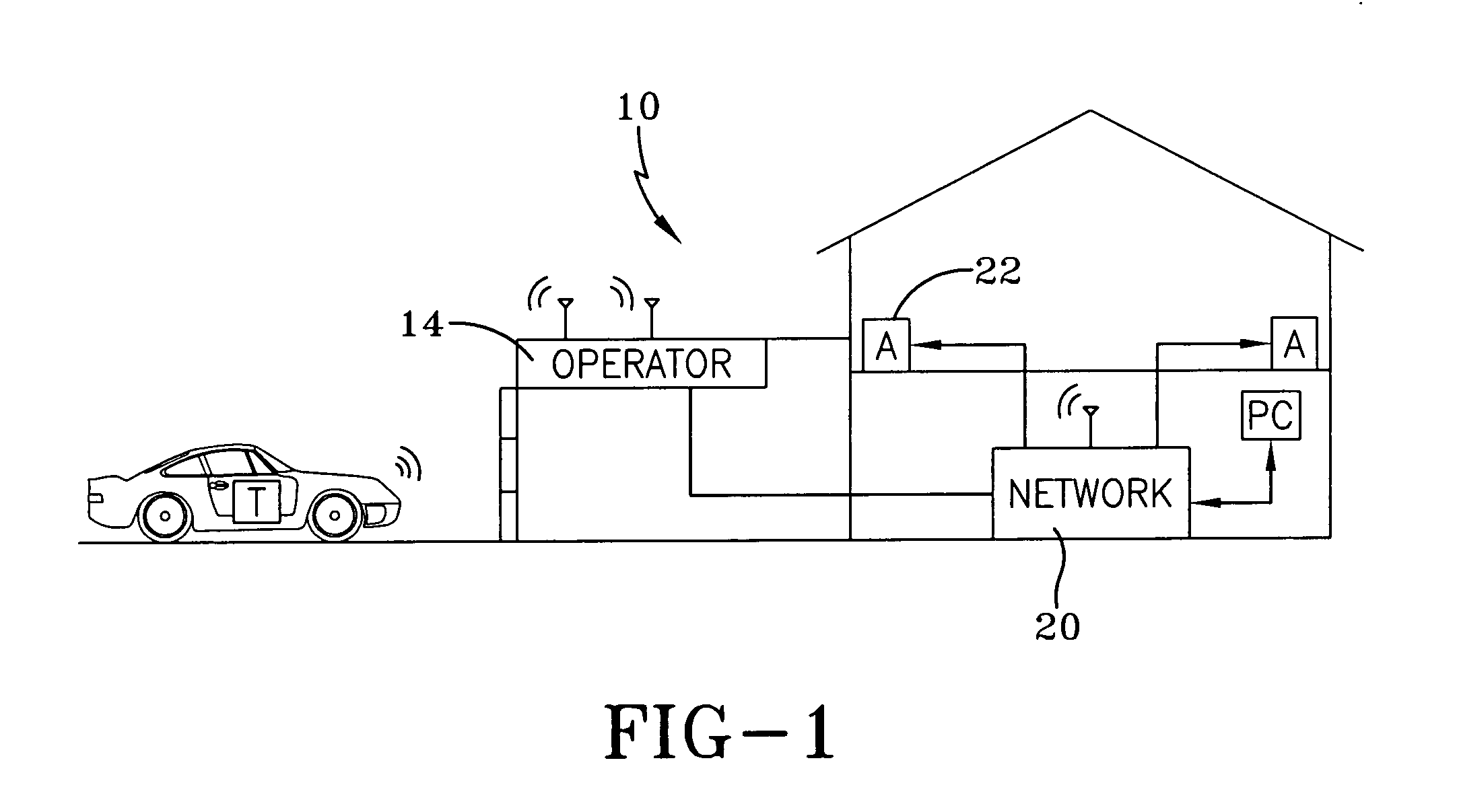
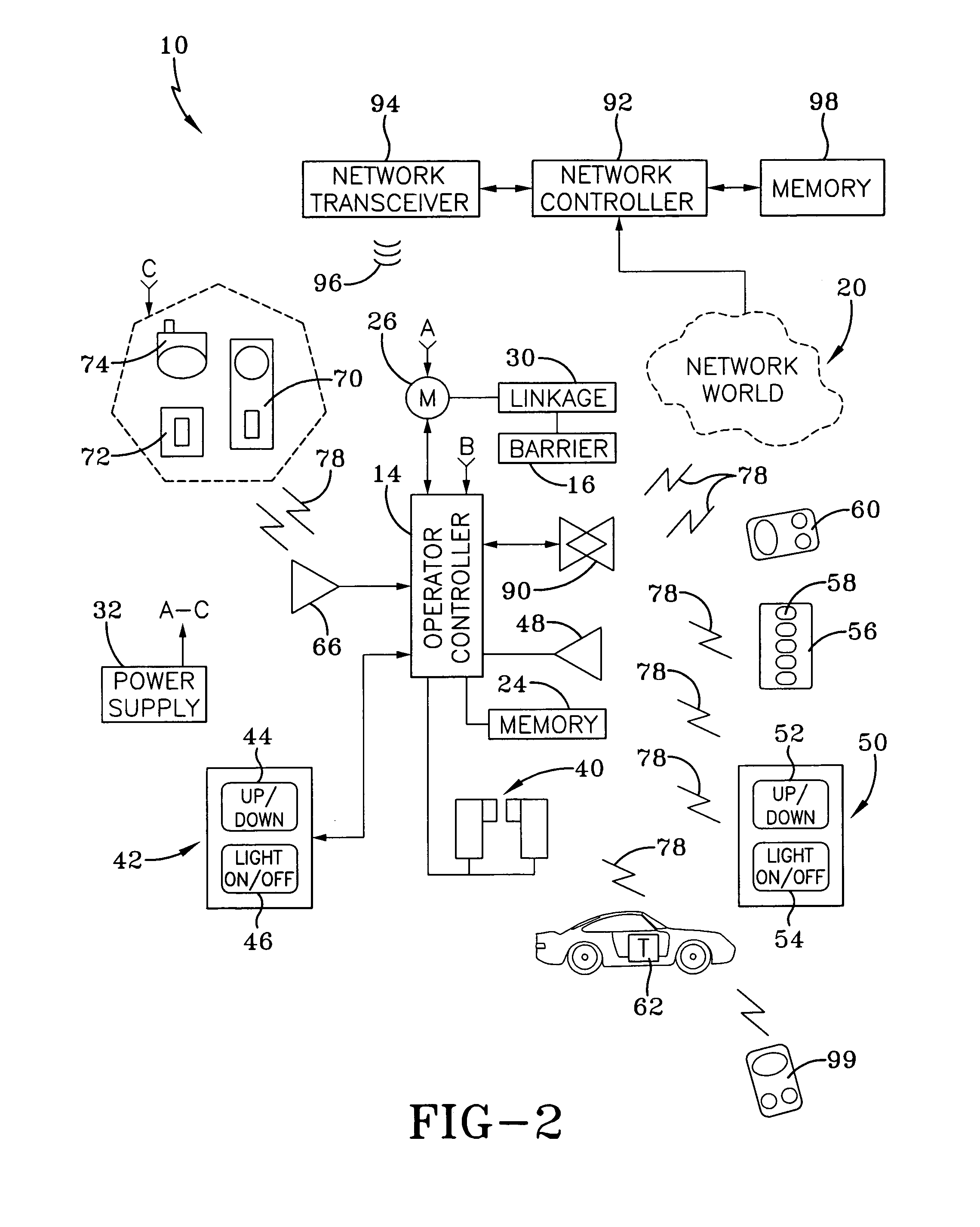
[0017] Referring now to the drawings and, in particular, to FIG. 1, it can be seen that a networked movable barrier operator system is designated generally by the numeral 10. Generally, the operator system 10 is utilized much like a movable barrier operator system but with additional features that allow for communications to be exchanged with a network and network transmitters in addition to local transmitters. As is common with most operator systems 10, the system 10 is installed in a building, such as a garage, house, factory, or warehouse; or the system 10 may be employed in a gated community wherein a single gate allows access to multiple users. Each operator system includes an operator controller 14 which is a microprocessor-based device that receives and generates wired or wireless signals; and includes the necessary hardware, software and memory for enabling the system. The operator controller 14 includes the ability to process “local” signals from transmitters and the like, ...


PUM


Abstract

A networked movable barrier operator for moving a barrier between limit positions including a motor attachable to the barrier, at least one non-network device, and at least one network device. A controller is connected to the motor and communicates operational signals between the non-network device and the network device to the motor, and communicates operational signals between the motor and the non-network device and the network device.

Description

TECHNICAL FIELD [0001] The present invention is generally related to a home network interface incorporated into a movable barrier operator. In particular, the present invention is related to a movable barrier operator that communicates with both non-network transmitters and network transmitters, wherein the network interface is capable of controlling, acquiring data from, and posting data to other network devices anywhere in the world, while also controlling operation of a movable barrier. BACKGROUND ART [0002] A movable barrier operator contains control electronics and an electric motor which is linked to a movable barrier such as garage doors, curtains, retractable awnings, gates and the like for the purpose of opening and closing the barrier. Known operators are capable of receiving “local” signals for receiving and processing requests or commands to move the barrier. Requests to move the barrier can be transmitted by either hard wired signals, or via wireless transmissions from ...

Claims


Application Information

Patent Timeline
Patent Type & Authority Applications(United States)
IPC IPC(8): H04Q1/00G05B19/00
CPCG05B19/0428G05B2219/24048G07C2009/00928G05B2219/2628G05B2219/24067
Inventor RODRIGUEZ, YAN
Owner WAYNE DALTON CORP
Learn More