
Plasma display panel assembly and method of fabricating the same

a technology of plasma display panel and exhaust tube, which is applied in the direction of gas exhaustion means, gas discharge sealing, television systems, etc., can solve the problems of limited noise reduction by using vibration absorbent, vibration and noise generated in the panel assembly,

Inactive Publication Date: 2006-05-11
SAMSUNG SDI CO LTD
View PDF2 Cites 6 Cited by
  • Summary
  • Abstract
  • Description
  • Claims
  • Application Information

AI Technical Summary

Problems solved by technology

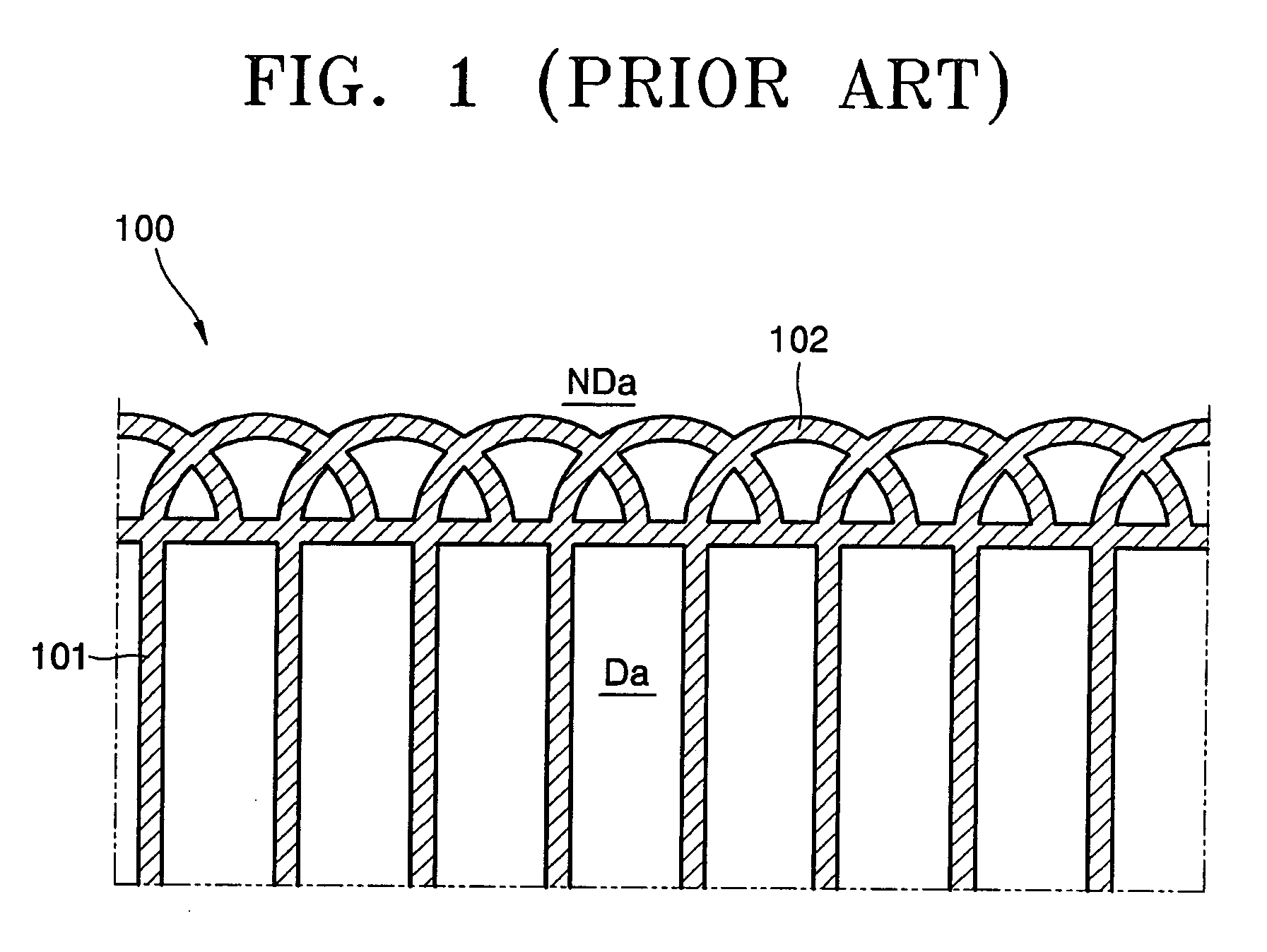
Accordingly, when the rear panel is sealed with the front panel, a gap may be generated between the front panel and the dummy barrier rib 102, which may cause vibration and noise when driving the panel.
Consequently, noise may be generated in the panel assembly.
In order to prevent noise, silicon or soft plastic may be used as a vibration absorbent to prevent the panel assembly from vibrating, however, the amount of noise that may be reduced by using the vibration absorbent is limited.
However, the noise generated in the panel assembly may not be completely removed by the other conventional methods.
Recently, a cause of the noise has been considered to be related to an exhaust tube that is installed to perform a vacuum exhaustion process.
More noise is generated on the portion where the exhaust tube is installed since the exhaust tube echoes the noise generated in the panel assembly.

Method used


Image

  • Plasma display panel assembly and method of fabricating the same
  • Plasma display panel assembly and method of fabricating the same
  • Plasma display panel assembly and method of fabricating the same

Examples


Embodiment Construction

[0024] The invention is described more fully hereinafter with reference to the accompanying drawings, in which embodiments of the invention are shown. This invention may, however, be embodied in many different forms and should not be construed as limited to the embodiments set forth herein. Rather, these embodiments are provided so that this disclosure is thorough, and will fully convey the scope of the invention to those skilled in the art. In the drawings, the size and relative sizes of layers and regions may be exaggerated for clarity.

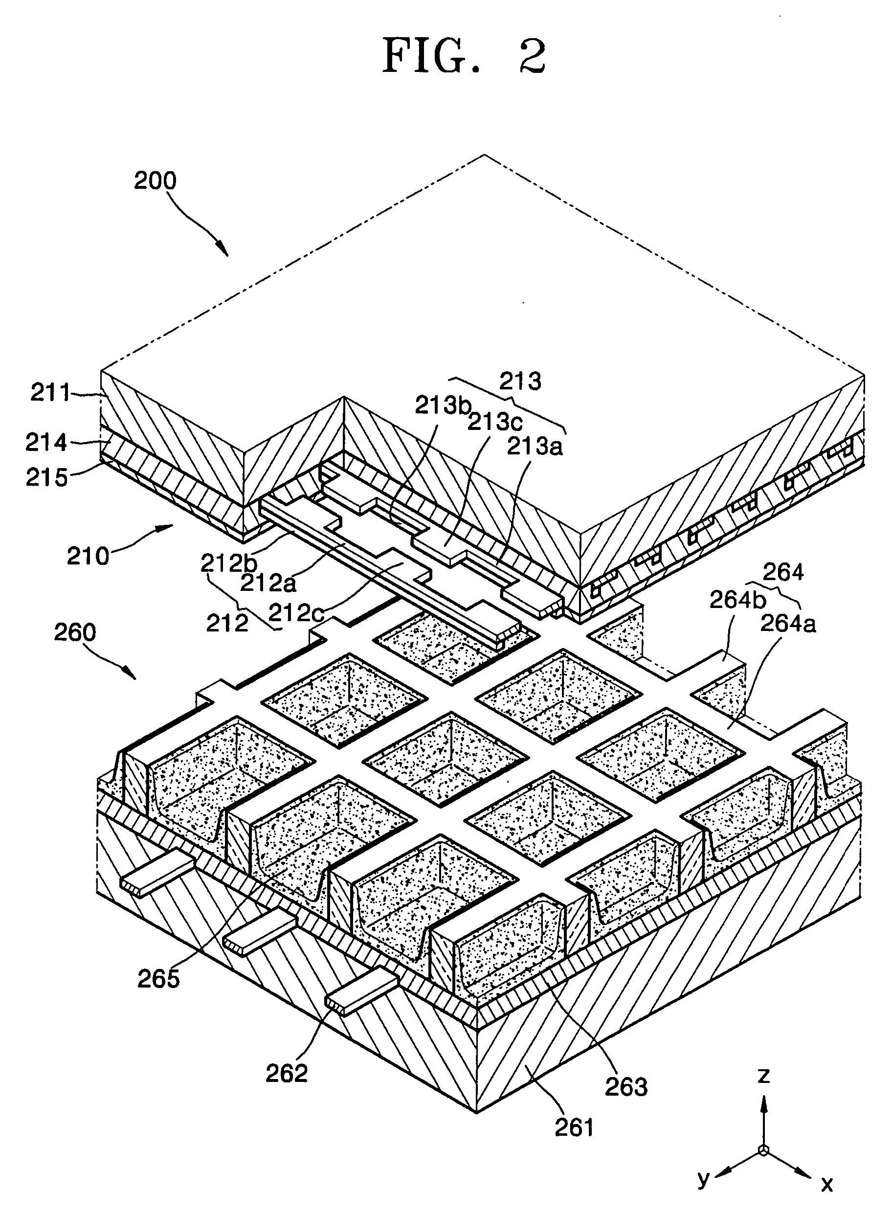
[0025]FIG. 2 shows a part of a plasma display panel 200 according to an exemplary embodiment of the present invention.

[0026] Referring to FIG. 2, the plasma display panel 200 includes a front panel 210 and a rear panel 260 arranged substantially parallel to each other. A frit glass is applied on edges of facing surfaces of the front and rear panels 210 and 260 to form a sealed inner space.

[0027] The front panel 210 includes a front substrate 211,...


PUM


Abstract

A plasma display panel includes a front panel and a rear panel coupled with each other, and an exhaust tube is arranged on the plasma display panel. The plasma display panel and the exhaust tube satisfy L / T≦2, L is a length of the exhaust tube, and T is a thickness of the plasma display panel.

Description

CROSS-REFERENCE TO RELATED PATENT APPLICATIONS [0001] This application claims priority to and the benefit of Korean Patent Application No. 10-2004-0083502, filed on Oct. 19, 2004, which is hereby incorporated by reference for all purposes as if fully set forth herein. BACKGROUND OF THE INVENTION [0002] 1. Field of the Invention [0003] The present invention relates to a plasma display panel assembly, and more particularly, to an exhaust tube of a plasma display panel assembly. [0004] 2. Discussion of the Related Art [0005] Generally, a plasma display panel assembly is a flat panel display device, in which discharge electrodes are formed on facing substrates. A discharge gas is injected into a discharge space, and a voltage is applied to the discharge electrodes to generate a discharge, thereby generating ultraviolet rays, which excite a phosphor layer to emit light for displaying images. [0006] The plasma display assembly may be formed by coupling a front panel and a rear panel to ea...

Claims


Application Information

Patent Timeline
IPC IPC(8): H04N5/64H01J9/385H01J11/24H01J11/46H01J11/48H01J11/54
CPCH01J11/12H01J11/54H01J17/20H01J17/16H01J11/10
Inventor SONG, JUNG-SUK
Owner SAMSUNG SDI CO LTD
Learn More