Renewable energy wave pump

a technology of energy wave pump and energy wave, which is applied in the direction of mechanical equipment, machines/engines, electric generator control, etc., can solve the problem that the u.s. consumes nearly a quarter of the world power supply

Inactive Publication Date: 2006-05-11
AYNTRAZI SHAMIL SAMI
View PDF3 Cites 12 Cited by
  • Summary
  • Abstract
  • Description
  • Claims
  • Application Information

AI Technical Summary

Problems solved by technology

America consumes nearly a quar

Method used


Image

  • Renewable energy wave pump
  • Renewable energy wave pump
  • Renewable energy wave pump

Examples


Embodiment Construction

[0060] When you see an undulation go by, you think of it as the water moving. Well, it's not the water it's the kinetic and potential energy within the water that's making it seem to move. The energy within the undulation has a high flow (O) at a low head (h). The idea is to pull out this energy to a low (O) at a higher head (H) and collect enough Q suitable for operating a large hydro-turbo-generator. A series of deep-water REWP's are installed along the path of the undulation, each pulling out a portion of the undulation energy until ninety percent of total undulation energy is pulled out and changed to a lower Q at a higher head.

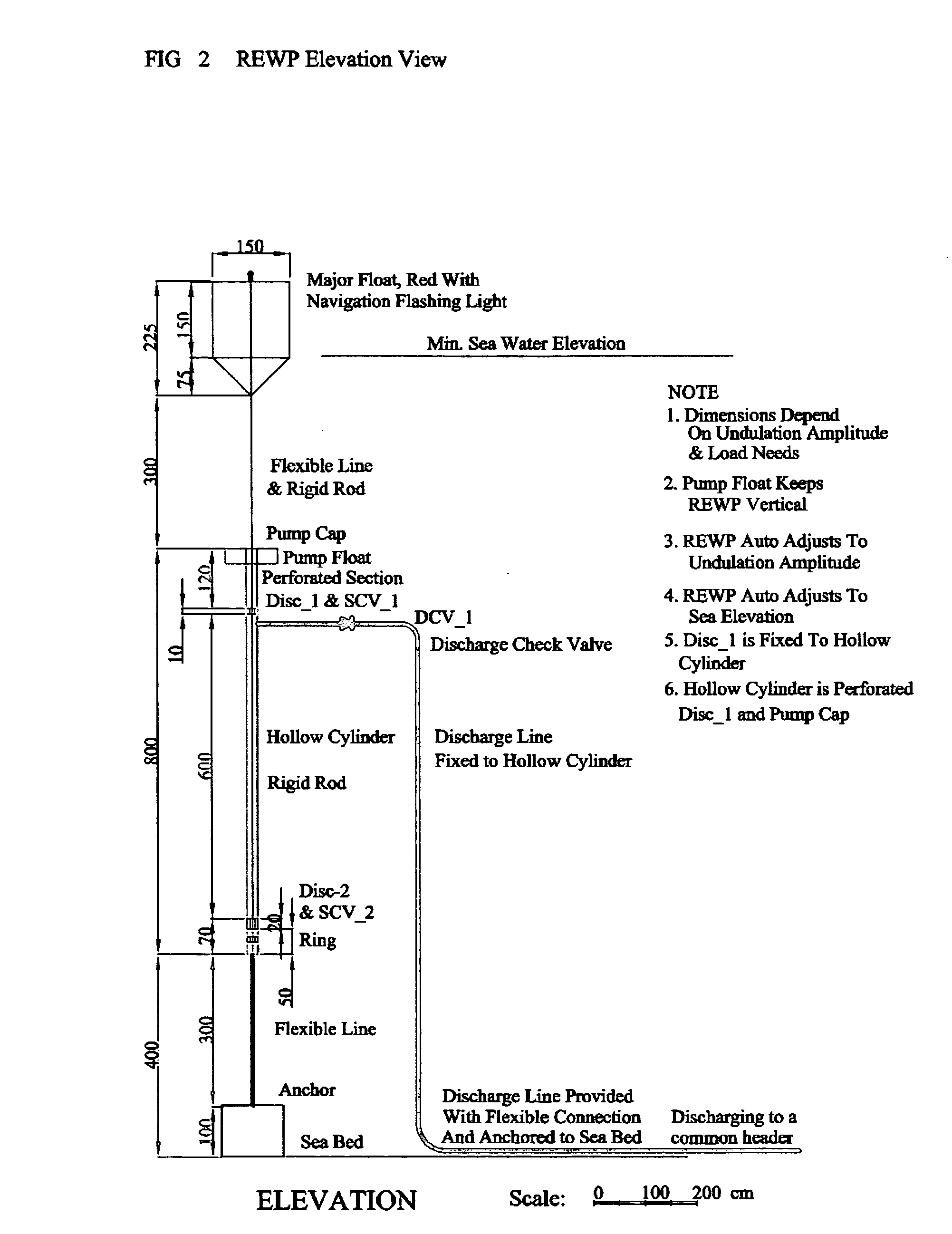
[0061] As the undulation has an apparent motion from left to right, the following actions take place as shown in FIG. 4; Schematic Flow Diagram, page 4 / 6: [0062] 1. The Major Float oscillates up and down following the contour of the undulation. [0063] 2. The Major Float has a flexible connection to the REWP rigid rod to allow for limited horizontal swing...


PUM


Abstract

A renewable energy electric power generating system consisting of Renewable Energy Wave Pumps, located under water, anchored to the sea bed, auto regulating to variable sea elevations and undulation heights, efficient, simple construction and resistant to storms, operate by using the law of conservation of energy to change, a large quantity of water at low head found in a surface undulation, into a lower water quantity at a much higher head, collecting this high head water into a piping network and a common header anchored to the sea bed, provided with a stand pipe and reservoir, and feeds directly into a hydro-turbo generator located on or off shore to produce renewable cheap electric power with zero emissions and independent of oil prices, optimizing land use for power plants, and providing a navigation-safe and a free Floating Break Water Structure for shore line protection

Description

[0001] Periodic undulations in an expanse body of water are a renewable energy source having both potential and kinetic energy in the form of a large volume of fluid at a small head (undulation height). The idea is to change this energy to a usable form. Using the law of conservation of energy, this large volume of fluid undulation is exchanged by a small volume of fluid pulled up to a much higher level, thus pulling out part of the fluid undulation energy. [0002] The apparatus proposed for this energy exchange is herein called a Renewable Energy Wave Pump-REWP. Installing a field of REWP's up to 10 in line with apparent path of the fluid undulation would pull out and level pulses of energy up to ninety percent of the undulation energy. [0003] Installing fields of REWP's up to 1,500 across the apparent path of the fluid undulation, collecting this fluid in a piping network with suction and discharge control valves, and discharging into a hydro-turbine, may produce power of up to 100...

Claims


Application Information

Patent Timeline
IPC IPC(8): F03B13/12F03B13/10H02P9/04
CPCF03B13/189Y02E10/38Y02E10/30
Inventor AYNTRAZI, SHAMIL SAMI
Owner AYNTRAZI SHAMIL SAMI
Why Eureka
Try Eureka