
Fiber drop terminal

a technology of fiber drop terminal and fiber drop, which is applied in the field of communication networks, can solve the problems of insufficient bandwidth for some users, increased cost of deployment and/or maintenance of technologies, and increased bandwidth for users

Active Publication Date: 2006-05-04
COMMSCOPE TECH LLC
View PDF99 Cites 296 Cited by
  • Summary
  • Abstract
  • Description
  • Claims
  • Application Information

AI Technical Summary

Benefits of technology

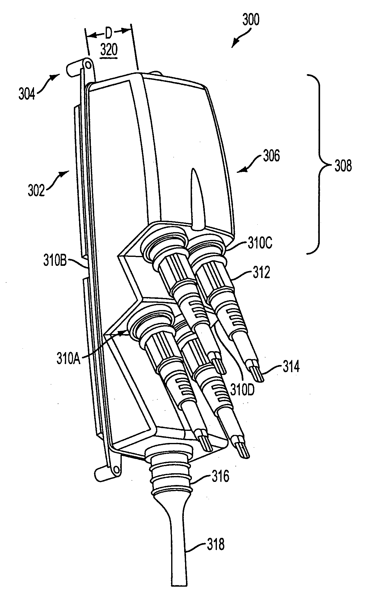
[0012] In accordance with another implementation, a fiber drop terminal is provided. The fiber drop terminal may include a first face having a first plurality of output receptacles having a first mounting angle with respect to the first face. The fiber drop terminal may include a second face having a second

Problems solved by technology

Users may, however, demand even higher bandwidths.
The above technologies may have inadequate bandwidth for some users and/or these technologies may be relatively expensive to deploy and/or maintain.
At times, the plastic used for the enclosure may fatigue and/or crack leading to water and/or water vapor penetration into the interior of the enclosure.
For example, gasket material may be of an inadequate durometer to provide a weather-tight seal between an enclosure body and/or an enclosure base.
Existing fiber drop terminals may not have sufficient interior space to allow fibers within the enclosures to bend with a radius of at least an industry and/or manufacturer recommended minimum bend radius.
When optical fibers are bent with a radius of less than an industry and/or manufacturer recommended minimum, such as 1.75 inches, o

Method used


Image

  • Fiber drop terminal
  • Fiber drop terminal
  • Fiber drop terminal

Examples


Embodiment Construction

[0048] Reference will now be made in detail to exemplary implementations of the present invention, examples of which are illustrated in the accompanying drawings. While exemplary implementations are provided, other implementations are possible in light of the specification. As such, changes may be made to the exemplary implementations described herein without departing from the spirit and scope of the invention. The following detailed description does not limit the invention; but instead, the scope of the invention is defined by the appended claims and their equivalents. Wherever possible, the same reference numbers may be used throughout the drawings to refer to the same or like parts.

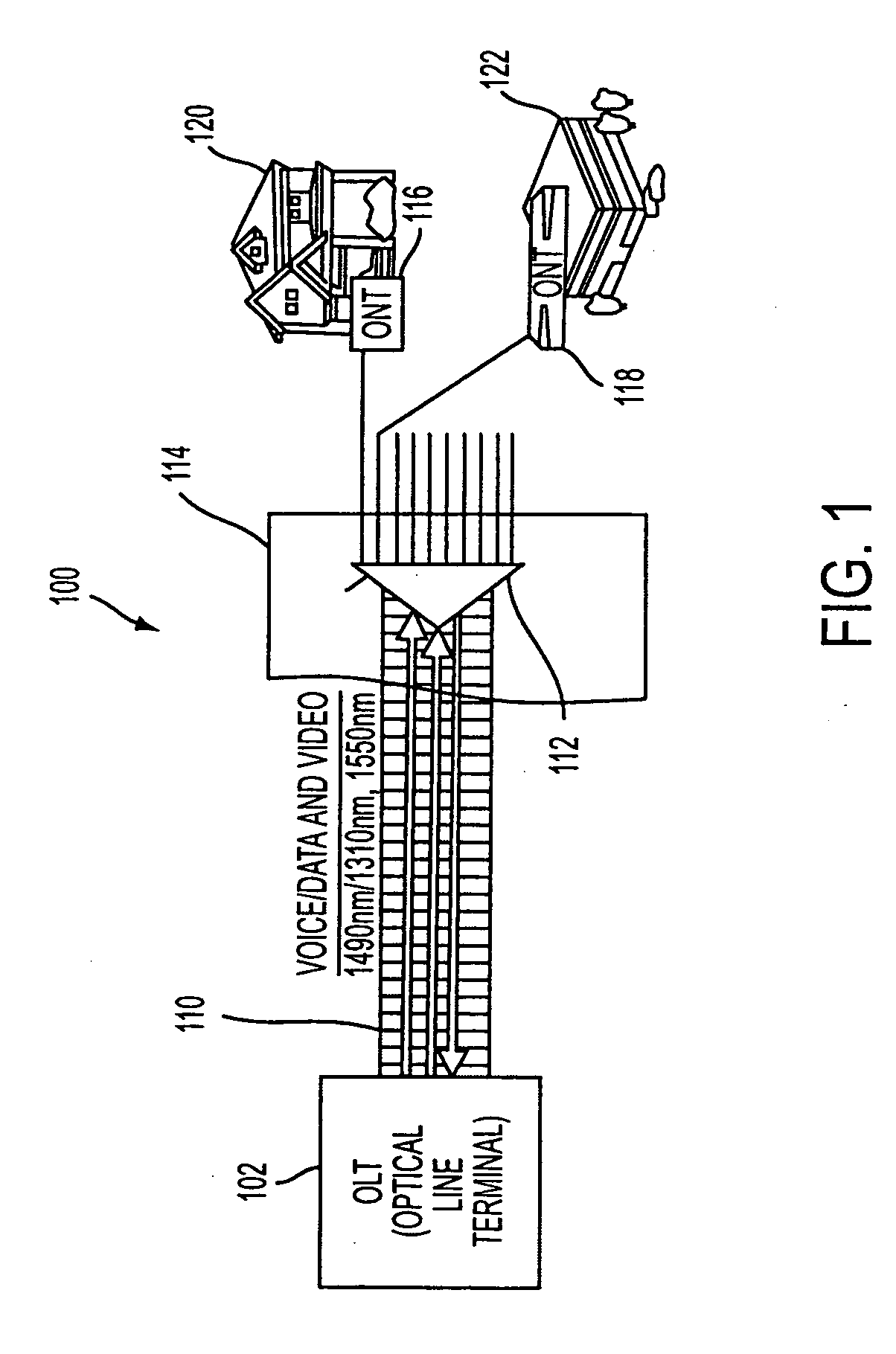
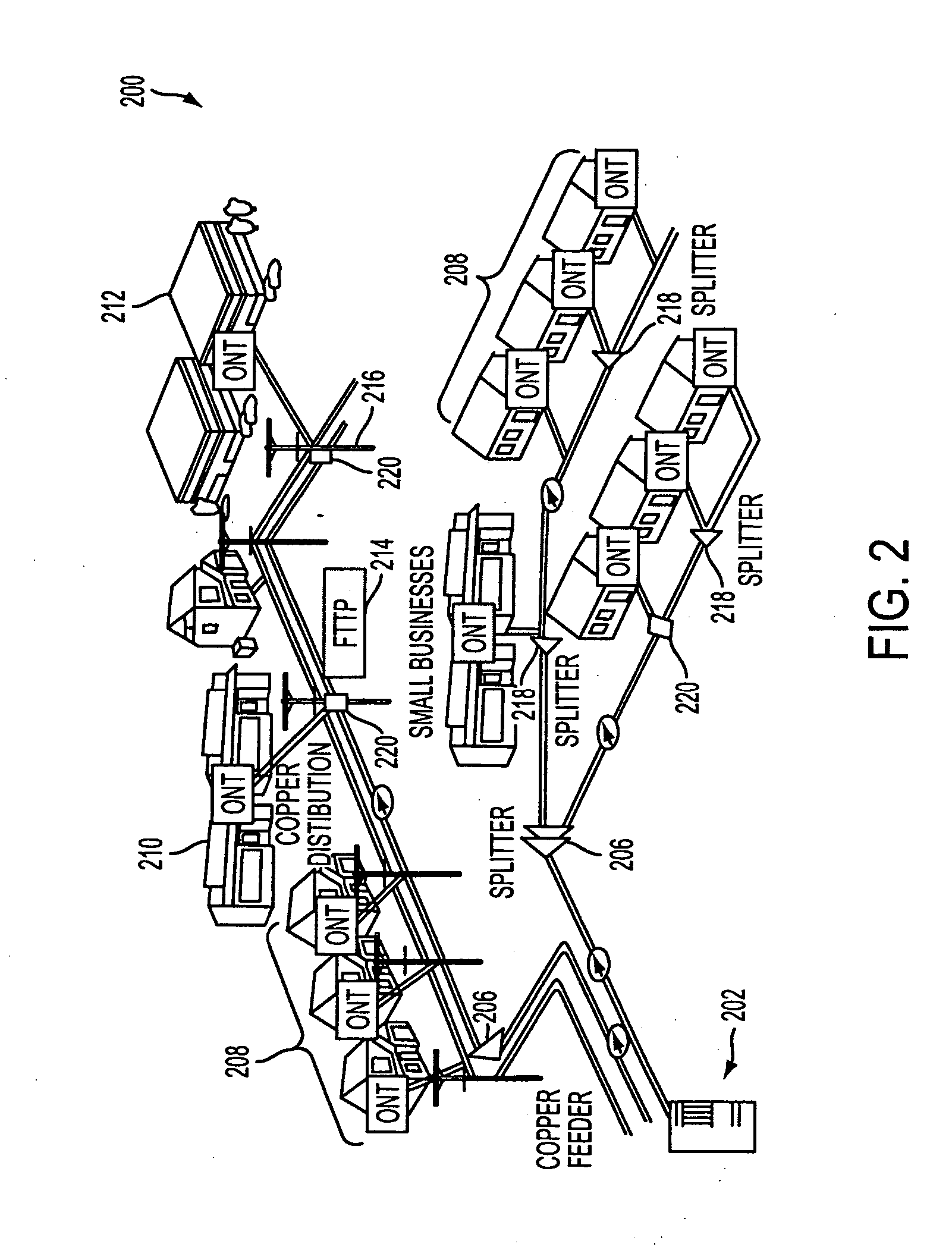
[0049]FIG. 1 illustrates a first schematic representation of an exemplary broadband access network 100 that may include PON components in an implementation consistent with the principles of the invention. Network 100 may include an optical line terminal (OLT) 102, a voice input 104, a data input 106,...


PUM


Abstract

A fiber drop terminal may include a housing having an outer surface containing a plurality of receptacles. The housing may include a lower surface and an inner cavity. The fiber drop terminal may include a fiber storage cavity occupying a portion of the inner cavity. The storage cavity may store a plurality of fiber coils at an angle.

Description

RELATED APPLICATION [0001] This application claims priority under 35 U.S.C. §119(e) based on U.S. Provisional Patent Application Ser. No. 60 / 624,582, filed Nov. 3, 2004, the entire content of which is hereby incorporated herein by reference.FIELD OF THE INVENTION [0002] The present invention relates generally to communication networks and, more particularly, to fiber drop terminals for use in optical communications networks. BACKGROUND OF THE INVENTION [0003] Residential, corporate, government, educational, and institutional users of communication services may desire high bandwidth connections to a communications network in order to send and receive data at high rates of speed. High bandwidth communications may allow users to take advantage of advanced communication capabilities, such as voice-over-internet protocol (VoIP) communications, interactive gaming, delivery of high resolution video, such as high definition television (HDTV), as well as the transmission and / or reception of ...

Claims


Application Information

Patent Timeline
IPC IPC(8): G02B6/00G02B6/36
CPCG02B6/4466G02B6/3897G02B6/4441H04B10/07G02B6/475H04B10/25891G02B6/4446G02B6/3885G02B6/4442G02B6/4444G02B6/4457
Inventor REAGAN, RANDYGNIADEK, JEFFREYNOONAN, MICHAELBAREN-BOYM, MICHAEL
Owner COMMSCOPE TECH LLC
Learn More