Hearing-aid anchoring element

Active Publication Date: 2006-05-04
OTICON MEDICAL
View PDF4 Cites 22 Cited by
  • Summary
  • Abstract
  • Description
  • Claims
  • Application Information

AI Technical Summary

Benefits of technology

[0015] The fixture of the present invention has a depth of the thread that is at least 10% of the maximum diameter of the threaded portion of the fixture. The depth of the threaded portion is however not greater than 20% of the maximum diameter of the thread of the fixture. By designing the depth of the thread in this interval, several significant and surprising advantages can be achieved for a fixture intended to be used for anchoring direct bone conduction hearing aids. The improvements are both on the microscopic and the macroscopic level. On a microscopic level, the increased surface offers an increased contact surface between the bone tissue and the fixture and this will contribute to a higher removal torque if forces directed to screw out the fixture from the bone is applied to the fixture when the fixture is osseointegrated. On a macroscopic level, the increased depth of the thread results in a firmer grip in the bone if trying to pull the fixture out of the hole.
[0029] In a preferred embodiment the fixture of the present invention presents at least one groove extending at least one turn on the side of the flange facing the threaded portion. This arrangement will acts as a micro thread in contact with the bone. Since bone resorbtion starts in the periphery of the flange, this arrangement will hinders the bone resorbtion under the flange. This is a similar effect as the well know effect of the thread of the threaded portion for existing fixtures, where the The thread is hindering the bone resorbtion from going further down along the threaded portion in contra distal direction.

Problems solved by technology

A thread deeper than this might also complicate the manufacturing procedure for the fixture.

Method used


Image

  • Hearing-aid anchoring element
  • Hearing-aid anchoring element
  • Hearing-aid anchoring element

Examples


Embodiment Construction

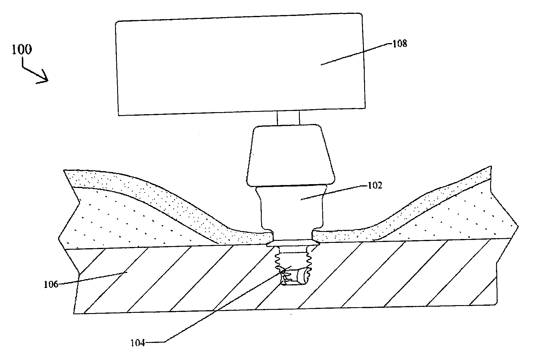
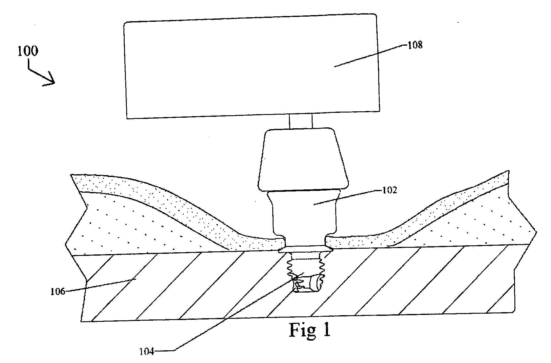
[0035]FIG. 1 is a side view of an illustrative example of a direct bone conduction hearing aid system 100 that has an abutment 102 with a fixture 104 that is screwed into a skull bone 106 of a user. A hearing-aid device 108 converts sound into vibrations and the vibrations is transferred to the skull bone 106.

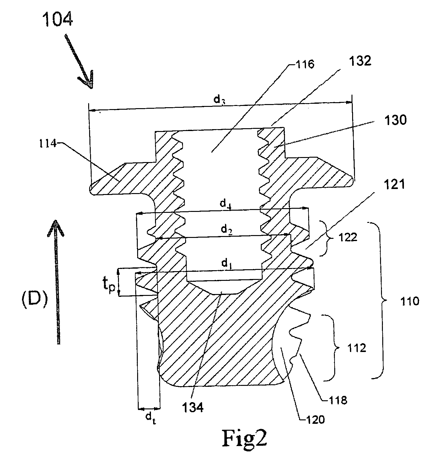
[0036]FIG. 2 is a cross-sectional side view and FIG. 4 is a perspective view of a preferred embodiment of the fixture 104. The fixture 104 has a threaded portion 110 having a maximum outer diameter d1 and an inner diameter d2. The thread has a depth dt and a thread pitch tp. The fixture has a conical outer portion 112 to facilitate the insertion of the fixture 104 into a hole in the skull bone 106.

[0037] An upper end of the fixture 104 has a radially outwardly protruding flange 114 with a diameter d3 to prevent the fixture 104 from being pushed into the skull. Preferably, the diameter d3 is greater than the diameter d2. An axial extension 130 has an axial threaded inner hole ...


PUM


Abstract

A hearing aid anchoring fixture (104) for anchoring a direct bone conduction hearing aid (108) to the skull bone (106), comprising a threaded portion (110) that has at least one cutting edge (118). Each cutting edge (118) has an adjacent cavity (120) having a volume Vc. The threaded portion (110) has a thread depth dt being half of the difference between the maximum outer diameter d1 of the threaded portion (120) and the inner diameter d2 of the thread, where dt is at least 10% of the maximum outer diameter d1 of the threaded portion (110) and where dt is less than 20% of the maximum outer diameter d1 of the threaded portion (110). The fixture (104) may be equipped with a flange portion (114) that has an outer diameter d3 being greater than the maximum diameter d1 of the threaded portion (110).

Description

TECHNICAL FIELD [0001] The present invention relates to an anchoring fixture for anchoring a direct bone-conduction hearing-aid to the skull bone. BACKGROUND OF THE INVENTION [0002] Bone conduction hearing aids are essential for the rehabilitation of patients suffering from hearing losses for which traditional hearing aids are insufficient. Direct bone conduction hearing aids have a vibrating transducer that transmits vibrations directly to a fixture anchored in the bone, i.e. the skin does not take part in the transmission of the vibrations from the vibrator to the fixture in the bone. The most common type of such devices consists of an external hearing aid with a vibrating transducer which, through a coupling, is connected to a skin-penetrating abutment that has an interconnection to a screw shaped fixture anchored in the skull bone. A direct bone conduction hearing aid system may however be designed in other ways. [0003] The fixture is usually made of titanium and is often design...

Claims


Application Information

Patent Timeline
IPC IPC(8): H04R25/00
CPCH04R25/606
Inventor WESTERKULL, PATRIK
Owner OTICON MEDICAL
Why Eureka
Try Eureka