
System and method for allocating power to loads

a technology of power allocation and load, applied in the integration of power network operation systems, emergency power supply arrangements, transportation and packaging, etc., can solve the problems of generator stall, no load control or overload protection means, manual transfer switches also have no automatic means of controlling non-critical loads, etc., to maximize the use of available power and maximize power draw

Active Publication Date: 2006-04-06
SCHNEIDER ELECTRIC IT CORP
View PDF49 Cites 141 Cited by
  • Summary
  • Abstract
  • Description
  • Claims
  • Application Information

AI Technical Summary

Benefits of technology

The invention is about a system and method for controlling power to multiple loads from a primary and a backup power source. The system categorizes the loads as delayable or non-delayable, and allocates power accordingly. The system can also monitor and dynamically allocate power to the loads in real-time. The technical effects of the invention include improved efficiency and reliability of power distribution, as well as better protection against power loss or overload conditions.

Problems solved by technology

It may often be undesirable and often illegal or a code violation to leave the back-up generator permanently connected, in parallel with the utility power, to the residential electrical circuits.
However, such manual switches typically require the presence of an operator in order to accomplish the transfer.
This may be undesirable, in that some appliances (e.g., refrigerator or freezer, sump pump, etc.) should not go without power for extended periods of time and an operator may not be present at the time of a power outage to throw the switch.
In addition, manual transfer switches require the circuits to be manually switched to the generator, and as such have no means of load control or overload protection other than fuses or circuit breakers.
Manual transfer switches also have no automatic means of controlling non-critical loads.
Traditionally, a generator used with the switch is selected to match the load, however, an overload may cause the generator to stall or a circuit breaker to trip, or both.
Automatic transfer switches, if they do come with load-shedding features, generally require a complicated installation and configuration process.
A disadvantage of the system of the '432 patent, however, is that the use of all lower-priority loads may be prevented if a high-priority load requires power.
Generators may be used without transfer switches, however, this may be dangerous due to the possibility of backfeed into the utility power or shock hazard.
As discussed above, manual transfer switches do not provide any load control and are easy to overload.
Overloads can happen during initial inrush or during steady state operation.
Thus, power to critical loads may be turned off inadvertently, but permanently, through, for example, a non-critical load causing an overload.
Conventional generators also do not provide uninterrupted power because they typically require ten or more seconds to start.
UPS's do provide this capability, but they are typically designed as point backup and can be difficult to hardwire into building wiring.
Using both generators (for long term backup) and UPS's (for short term, uninterrupted power) is a good solution but is often difficult and expensive to design and install for the average homeowner or small business.
Existing methods and systems also do not account for the possibility of a third source (i.e. a UPS or a second generator), and are often expensive while providing only limited functionality.

Method used


Image

  • System and method for allocating power to loads
  • System and method for allocating power to loads
  • System and method for allocating power to loads

Examples


example 1

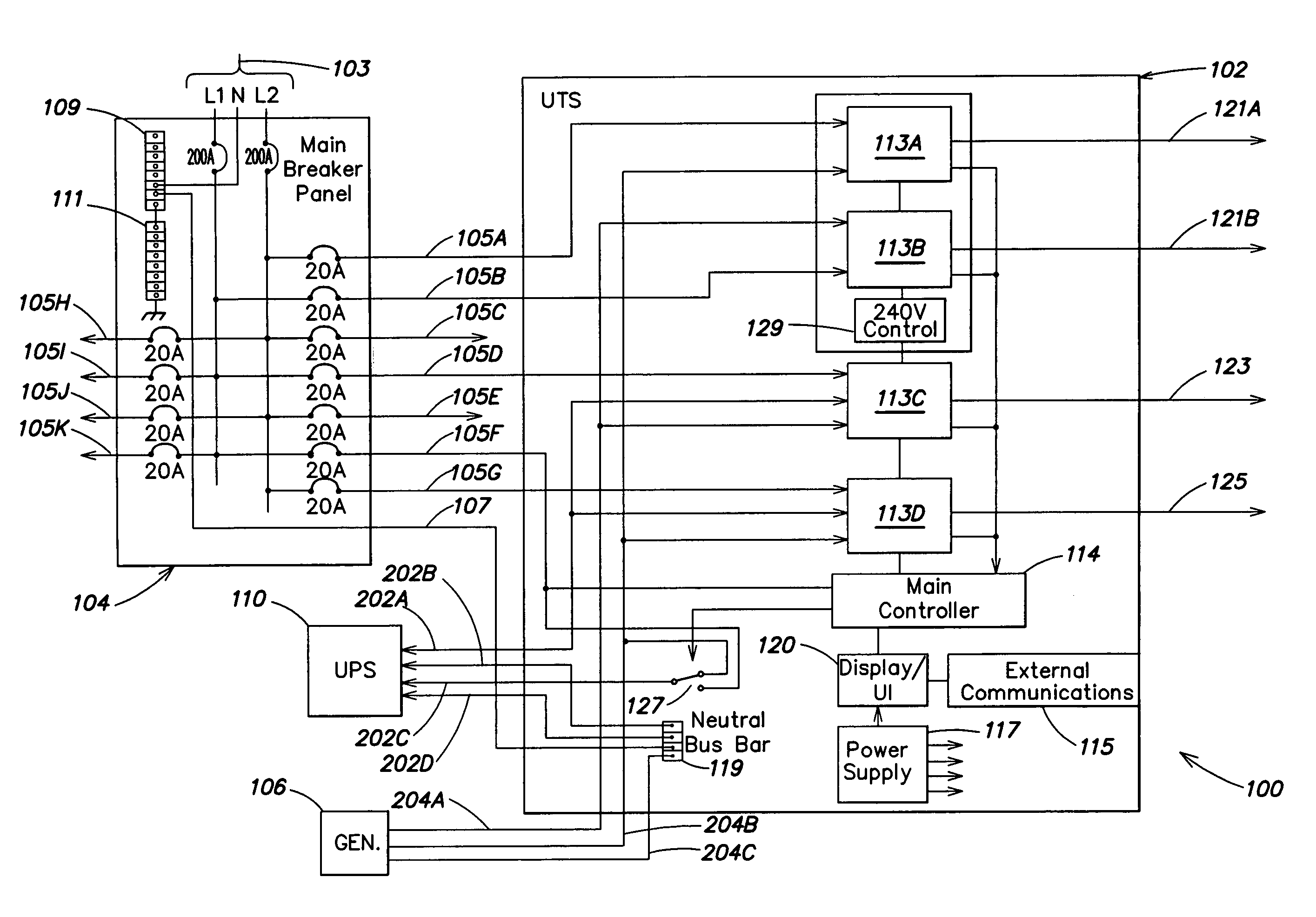
[0067] The source was loaded with 4490 W, consisting of a furnace, PC, refrigerator, microwave, and lights. The UTS recognizes that the load is beyond the continuous rating of the source and takes action. It measures the power being drawn by the two delayable loads as 1800 W by the furnace and 600 W by the refrigerator. The UTS disconnects power to the refrigerator, bringing the total load to 3890 W.

[0068] After a few minutes, the microwave turns off, decreasing the total load to 2390 W. The UTS recognizes the extra capacity available and reconnects the refrigerator, which raises the load to 3590 W.

example 2

[0069] The source was loaded with 4590 W, consisting of a furnace, PC, lights, and an operating garage door opener. The UTS recognizes that the load is beyond the continuous rating of the source and takes action. Since the furnace is the only delayable load currently drawing power, the UTS disconnects the furnace from the source. When the garage door opener completes its task, the load drops, so the UTS reconnects the furnace.

example 3

[0070] The source was loaded with 1190 W, consisting of a PC, refrigerator, and lights. The thermostat toggles on and activates the furnace. The inrush of the furnace creates a surge load of 6590 W. The UTS recognizes the surge rating of the source is being exceeded and takes action. It measures the power being drawn by the two delayable loads as 5400 W by the furnace (due to inrush) and 600 W by the refrigerator. The UTS disconnects power to the refrigerator, bringing the total load to 5990 W, within the surge rating of the generator.

[0071] Once the inrush requirement of the furnace is satisfied, the load settles to 2390 W. The UTS reconnects the refrigerator. The surge rating of the source handles the surge load of 4790 W. Once the inrush requirement of the refrigerator is satisfied, the load settles to 2990 W.


PUM


Abstract

A system and method for adaptive control of power among a plurality of loads based on a categorization of the loads as either delayable or non-delayable, wherein the non-delayable loads are preferably supplied power over the delayable loads. In one aspect, the system may be used to allocate limited power from a backup power source.

Description

BACKGROUND OF INVENTION [0001] 1. Field of Invention [0002] The present invention relates to systems and methods for efficiently applying power to a plurality of loads, including controlling switching of circuits between a primary power source and at least one secondary power source. [0003] 2. Discussion of Related Art [0004] Transfer switches are often used in association with portable or stand-alone electrical generators in order to switch a source of electricity for a load between a utility electricity supply and the back-up generator. [0005] For example, a private residence may normally receive its electrical power from a utility company. For various reasons, however (location in a region prone to severe weather, unreliable utility power, etc.), a homeowner may desire a back-up source of electrical power so that electrical devices and appliances in the residence can be powered during periods in which utility power is unavailable. The back-up generator may typically be a gasoline...

Claims


Application Information

Patent Timeline
Patent Type & Authority Applications(United States)
IPC IPC(8): H02H3/00
CPCH01H2300/018H02J3/14H02J9/06Y02B70/3225Y04S20/222Y04S20/20Y04S20/248Y02B70/30H02J2310/58
Inventor PAIK, NAM WOOKHAINES, LANCE PALMERDEOKAR, VISHWAS MOHANIRAJDONALDS, JAMES H.MANGANESE, MICHAEL
Owner SCHNEIDER ELECTRIC IT CORP
Learn More