
Visual documentation of micro-cracks during tensile coupon testing

a technology of tensile coupon and micro-cracks, applied in the field of composite materials and tensile coupon testing, can solve the problems of time-dependent micro-structural damage of many fiber-reinforced composite materials, reduced stiffness, and more serious damag

Active Publication Date: 2006-04-06
THE BOEING CO
View PDF16 Cites 19 Cited by
  • Summary
  • Abstract
  • Description
  • Claims
  • Application Information

AI Technical Summary

Benefits of technology

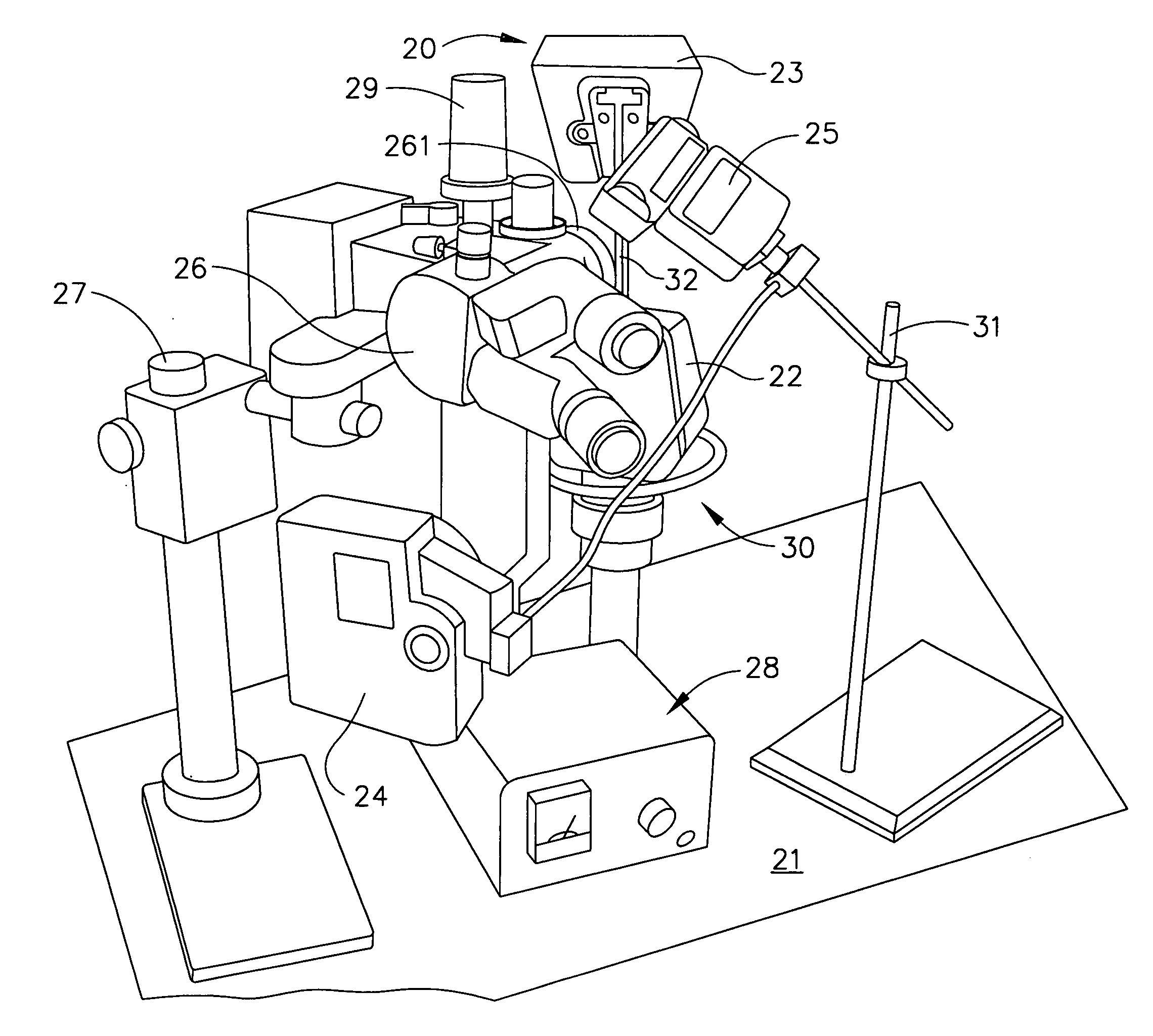
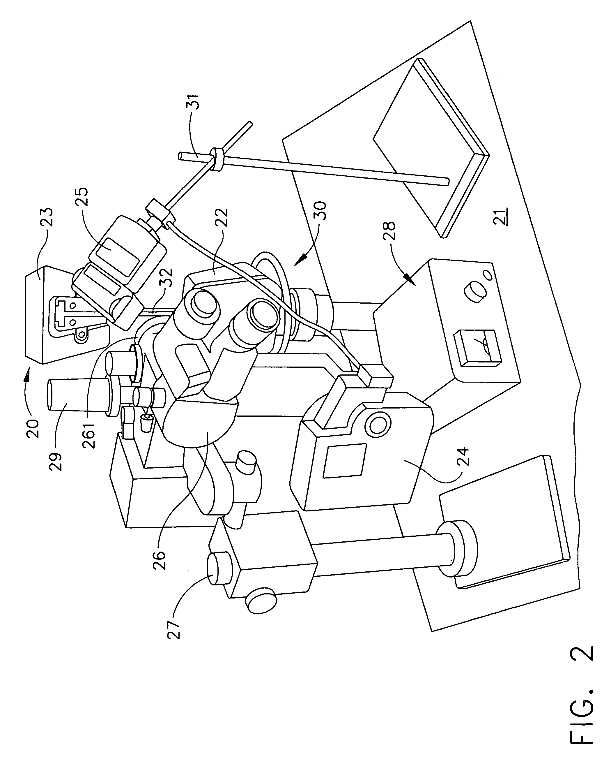
The present invention provides a method for determining the criteria that ensure the fatigue life of carbon-reinforced composite structures. This involves using a test unit and a specimen made of carbon-reinforced composite material with a strain gage attached. The method involves preparing the edge of the specimen for photo microscopy, inserting it into the test unit, and applying a tensile load to it while capturing images. The strain is measured using the strain gage and the resulting images are paired with a tensile strength-strain plot. The method can help prevent fatigue failures of carbon-reinforced composite structures by identifying the occurrence and growth of micro-cracks and providing the determined tensile stress to the aerospace industry.

Problems solved by technology

The technical problem addressed in this patent is the need for a reliable method to determine the presence and extent of micro-cracking in carbon-reinforced composite materials during tensile coupon testing without the need for destructive testing of many specimens. There is also a need to determine the load that causes the initial formation of micro-cracks (onset-of-damage) and to obtain test results without such testing.

Method used


Image

  • Visual documentation of micro-cracks during tensile coupon testing
  • Visual documentation of micro-cracks during tensile coupon testing
  • Visual documentation of micro-cracks during tensile coupon testing

Examples


Embodiment Construction

[0026] The following detailed description is of the best currently contemplated modes of carrying out the invention. The description is not to be taken in a limiting sense, but is made merely for the purpose of illustrating the general principles of the invention, since the scope of the invention is best defined by the appended claims.

[0027] Broadly, an embodiment of the present invention provides a test method for visual documentation of the formation and growth of micro-cracks in carbon-reinforced composite materials during tensile coupon testing. Contrary to the known prior art, only one specimen is needed to obtain information about formation and growth of micro-cracks in carbon-reinforced composite materials where currently destructive testing of many specimens is required. Furthermore, the test method according to one embodiment of the present invention will allow visually following the initial formation as well as the growth of existing micro-cracks under an increasing tensi...


PUM


Abstract

A test method for visual documentation of micro-cracks during tensile coupon testing includes the steps of: assembling a test unit; inserting a carbon-reinforced composite specimen having a prepared edge into the tensile coupon testing machine; illuminating the prepared edge of the specimen with a camera strobe light and a microscope light; applying a tensile load to the specimen; and capturing images (at 10% increments of the expected failing stress) of the prepared edge of the specimen with a digital camera that is attached to a stereomicroscope. Using the test method of the present invention photographic documentation of the formation and growth of micro-cracks in carbon-reinforced composite materials under tensile load is possible. The obtained data may be used to avoid or limit fatigue failure of carbon-reinforced structures used, for example, in the aerospace industry, for example, in spacecrafts and advanced military aircraft.

Description


Claims


Application Information

Patent Timeline
Owner THE BOEING CO
Learn More