Image distribution system and the control method therefor
a technology of image distribution system and control method, which is applied in the field of imaging equipment, can solve the problems that the camera control with a good response cannot be provided, and achieve the effect of improving the interoperability of the imaging device by the user
- Summary
- Abstract
- Description
- Claims
- Application Information
AI Technical Summary
Benefits of technology
Problems solved by technology
Method used
Image
Examples
first embodiment
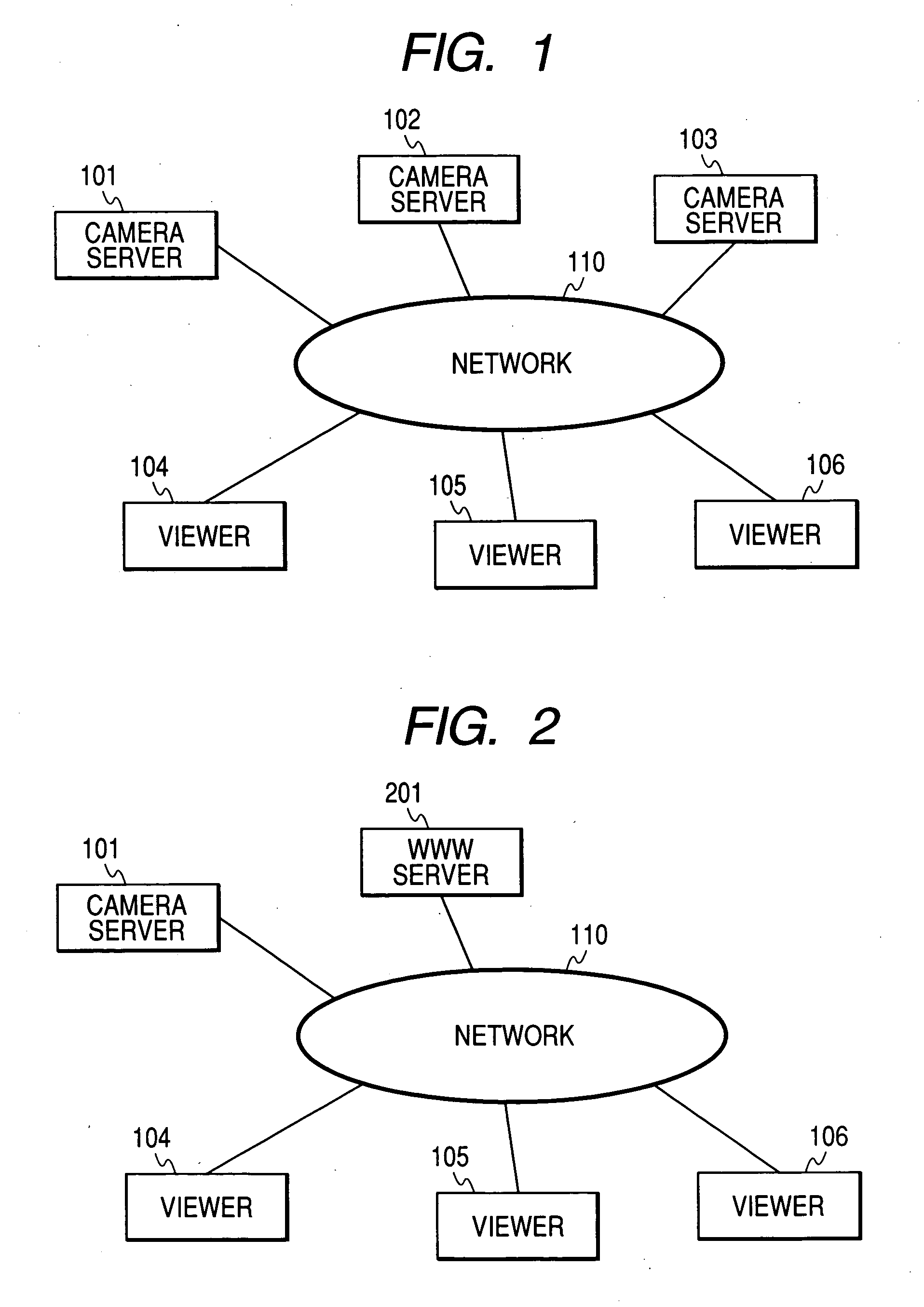
[0048] In a first embodiment of the present invention, an example is explained in which in a viewer disposed on the network, an operation capability of a camera provided by a camera server is switched in accordance with a network status. The viewer according to the first embodiment is characterized in that the viewer is provided with an extended camera control function which enables a control of the camera having a large granularity; and that the viewer provides coarse granularity camera control, instead of fine granularity camera control, in accordance with the network status.
[0049] With this characteristic, in a case of, for example, a cellular phone network where the large network delay occurs and a difference between the camera control and a camera video occurs, an operability of a user is improved and stress on a user is reduced.
[0050] Note that in the first embodiment, the fine granularity camera control is a primitive camera control such as panning, tilting, and zooming in ...
second embodiment
[0129] (An Example Where the Network Status is Reflected for Connection Negotiation Capability Exchange)
[0130] In the second embodiment of the present invention, as in the first embodiment described above, an example is explained in which in the camera server 101 disposed in the network 110, the camera control capability provided by the camera server 101 is switched in accordance with the status of the network 110. Especially, in the second embodiment, a capability exchange reflecting the network status is carried out at the time of the negotiation for connection from the viewer 104 to the camera server 101.
[0131] A form of connection of the network, a hardware configuration of each server and each client, and most of operations of each software according to the second embodiment are as explained in the first embodiment described above. However, a part of the operations of the viewer 104 as shown in the flow chart of FIG. 6 and a part of the operations of the camera control server...
third embodiment
[0141] (An Example of Operation Interface for Reflecting the Network Status in a Stepwise Manner)
[0142] In the third embodiment, just as described in the first embodiment, an explanation is made as to an example where in the camera server 101 disposed on the network 110, the camera control capability provided by the camera server 101 is switched in accordance with the network status such as the communication delay and the communication jitter.
[0143] Especially, the third embodiment is characterized in that the operation interface (GUI) which the viewer 104 provides changes from the fine granularity camera control to the coarse granularity camera control in a stepwise manner by the capability exchange reflecting the network status.
[0144] In the third embodiment, a form of connection of the network, a hardware configuration, and most of the operations of each software are as explained in the first embodiment. However, a part of the operations of the viewer 104 as shown in FIG. 6 an...
PUM
 Abstract
Description
Claims
Application Information
 - R&D
- Intellectual Property
- Life Sciences
- Materials
- Tech Scout
- Unparalleled Data Quality
- Higher Quality Content
- 60% Fewer Hallucinations
Browse by: Latest US Patents, China's latest patents, Technical Efficacy Thesaurus, Application Domain, Technology Topic, Popular Technical Reports.
© 2025 PatSnap. All rights reserved.Legal|Privacy policy|Modern Slavery Act Transparency Statement|Sitemap|About US| Contact US: help@patsnap.com


