
Method and apparatus for MIMO transmission optimized for successive cancellation receivers

a technology of successive cancellation and transmission method, applied in the field of communication system, can solve the problems of inapplicability, inability to optimize the limited feedback method for successive cancellation reception, and inability to choose the beamforming weight of the codebook

Active Publication Date: 2006-03-30
GOOGLE TECH HLDG LLC
View PDF6 Cites 137 Cited by
  • Summary
  • Abstract
  • Description
  • Claims
  • Application Information

AI Technical Summary

Benefits of technology

[0018] Also, some terms are used interchangeably in the specification: The terms, channel response, frequency selective channel profile, space-frequency channel response, are all referring to the channel response information needed by the base station in order to utilize closed-loop transmission techniques. The terms waveform and signal are also used interchangeably. A Subscriber device or Subscriber Station (SS) is sometimes referred to as a Mobile Station (MS) or simply a Mobile, and the invention applies equally to cases where the subscriber device is fixed or mobile (i.e., not fixed). A receiving device can be either a base station (BS), subscriber station (SS) or any combination thereof. Also, a tran

Problems solved by technology

However these limited feedback methods are not optimized for successive cancellation reception.
However these existing methods do not encompass how to choose codebook beamforming weights and also are not applicable when the number of transmit antennas is greater than the number of MIMO streams.

Method used


Image

  • Method and apparatus for MIMO transmission optimized for successive cancellation receivers
  • Method and apparatus for MIMO transmission optimized for successive cancellation receivers
  • Method and apparatus for MIMO transmission optimized for successive cancellation receivers

Examples


Embodiment Construction

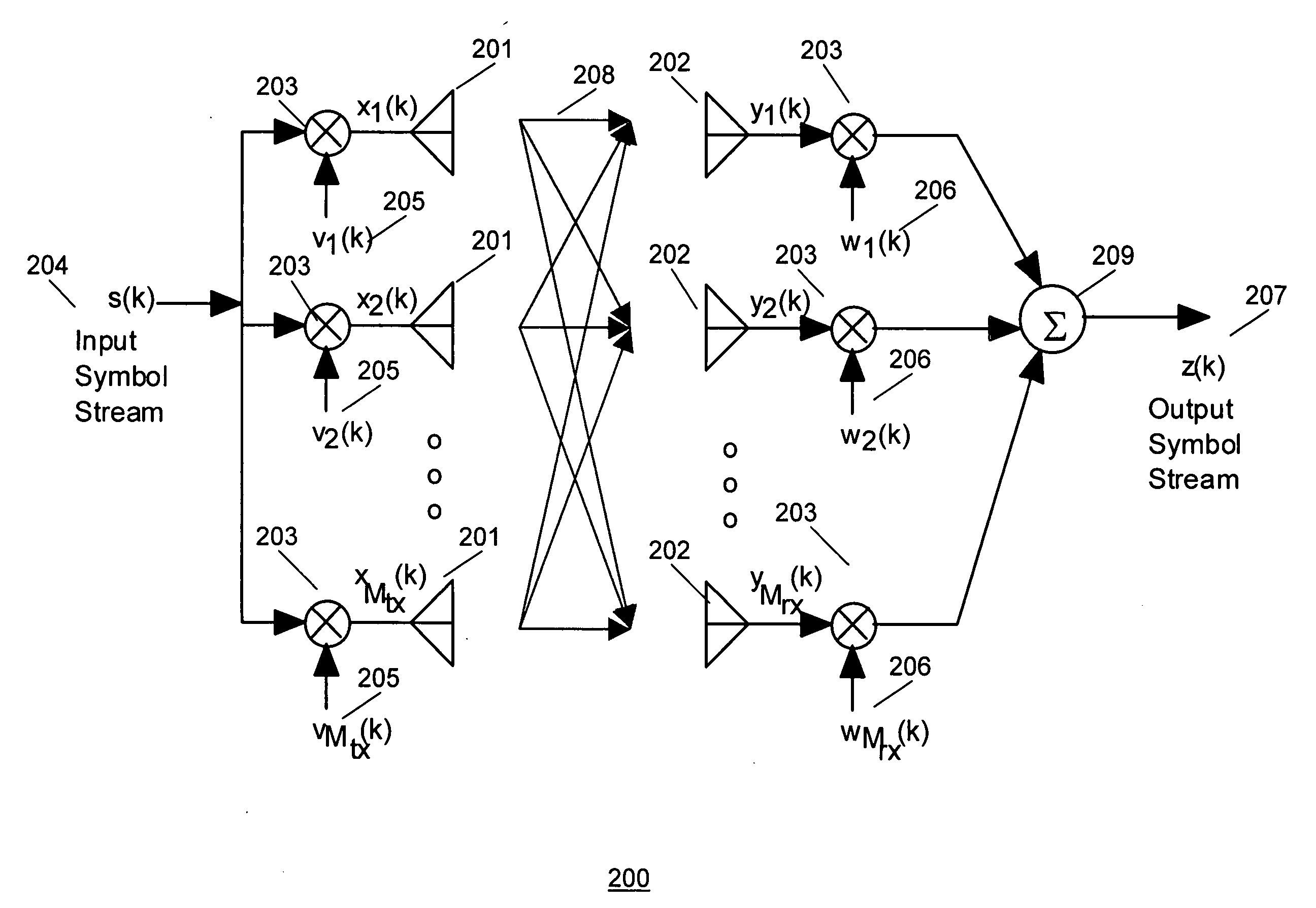
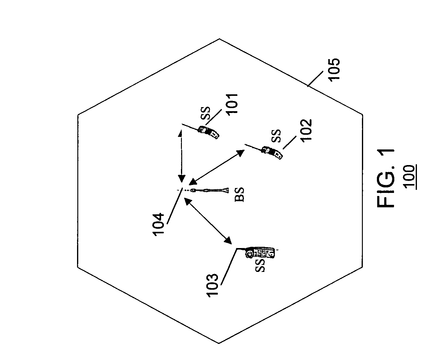
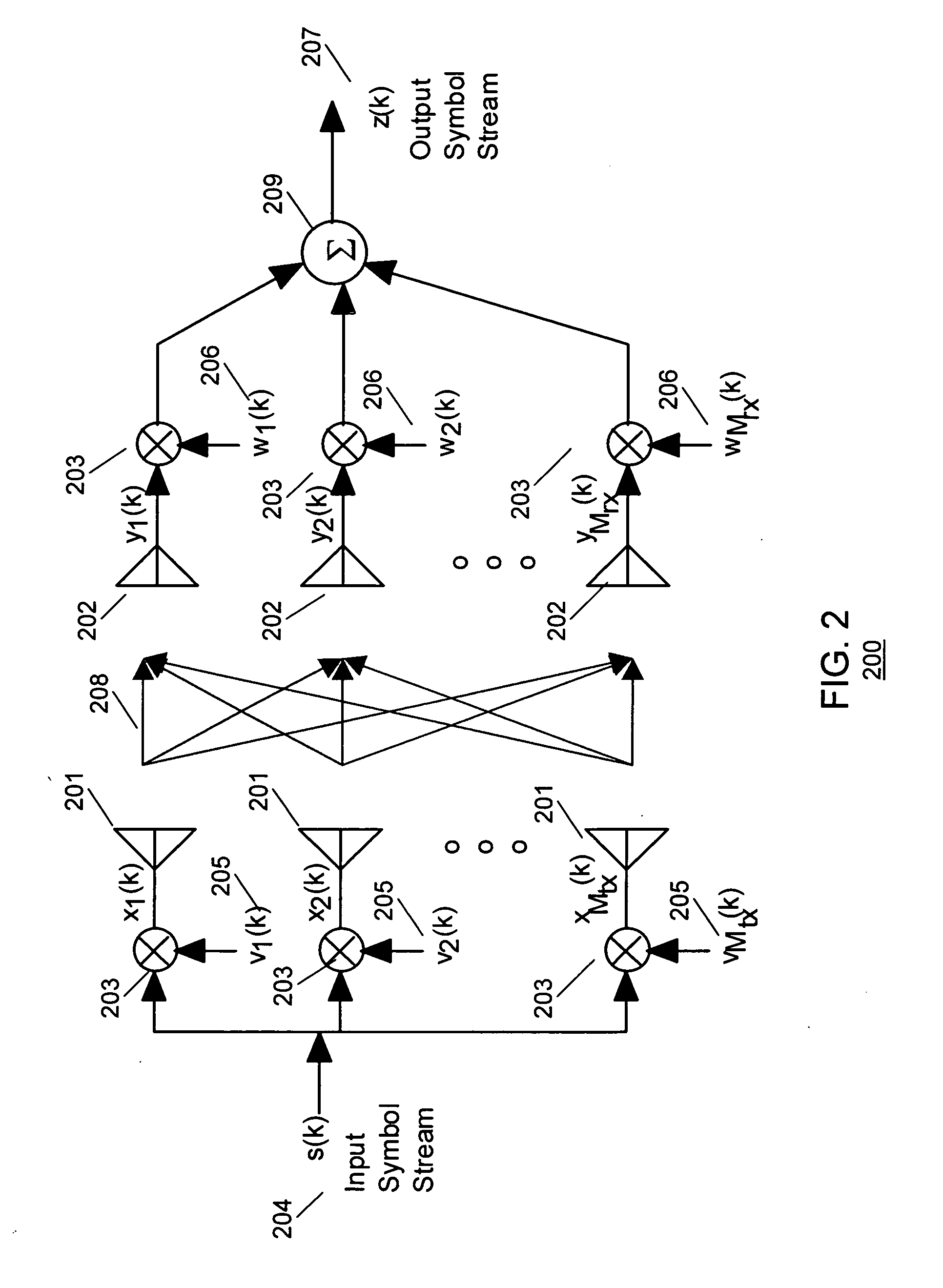
[0019] Turning now to the drawings, wherein like numerals designate like components, FIG. 1 is a block diagram of communication system 100 in which the present invention can operate. Communication system 100 comprises one or more cells 105 (only one shown) each having a base station (BS, or base station) 104 in communication with a plurality of subscriber stations (SSs) 101-103. If a transmission is to be performed on the downlink to SS 101, the BS 104 can be referred to as a source communication unit, and the SS 101 can be referred to as a target communication unit. If a transmission is to be performed on the uplink from SS 101 to the BS 104, SS 101 can be referred to as a source communication unit, and the BS 104 can be referred to as a target communication unit. In the preferred embodiment of the present invention, communication system 100 utilizes an Orthogonal Frequency Division Multiplexed (OFDM) or multicarrier based architecture including Adaptive Modulation and Coding (AMC)...


PUM


Abstract

A method for communicating a plurality of data streams between a transmitting device with multiple transmit antennas and a receiving device, is disclosed. The method comprises determining a list consisting of a subset of the multiple transmit antennas on which the transmitting device will transmit data, determining a set of power weightings, providing the set of power weightings and the list of the subset of the multiple transmit antennas to the transmitting device, weighting a plurality of data streams by the power weightings, and transmitting the power weighted data streams on the subset of the multiple transmit antennas to the receiving device. Another aspect of the invention comprises maintaining a codebook consisting of a plurality of transmit weight vectors at both the transmitting device and the receiving device. The method also comprises determining a list consisting of a subset of the plurality of transmit weight vectors which to use for transmitting the multiple data streams, determining a set of power weightings to be use for each data stream, providing the set of power weightings and the list of the subset of the plurality of transmit weight vectors to the transmitting device, and weighting the data streams by the power weightings and beamforming the data streams with the subset of the plurality of transmit weight vectors.

Description

FIELD OF THE INVENTION [0001] The present invention relates generally to communication systems, and in particular, to a method and apparatus for Multiple Input Multiple Output (MIMO) transmission. BACKGROUND OF THE INVENTION [0002] Multiple Input Multiple Output (MIMO) is a transmission method involving multiple transmit antennas and multiple receive antennas which promises to greatly increase the link capacity of wireless communication systems. Various transmission strategies require the transmit array to have some level of knowledge concerning the channel response between each transmit antenna element and each receive antenna element, and are often referred to as “closed-loop” MIMO. Obtaining full broadband channel knowledge at the transmitter is possible using techniques such as uplink sounding in Time Division Duplexing (TDD) systems and channel feedback in either TDD or Frequency Division Duplexing (FDD) systems. Limited feedback methods like feeding back message for antenna se...

Claims


Application Information

Patent Timeline
IPC IPC(8): H04Q7/00
CPCH04B7/04H04B7/0634H04B7/0636H04L27/2601H04B7/066H04B7/0691H04B7/0639
Inventor THOMAS, TIMOTHY A.BAUM, KEVIN L.VOOK, FREDERICK W.ZHUANG, XIANGYANG
Owner GOOGLE TECH HLDG LLC
Learn More