
Destination entry system with delayed elevator car assignment

Inactive Publication Date: 2006-03-30
OTIS ELEVATOR CO
View PDF4 Cites 24 Cited by
  • Summary
  • Abstract
  • Description
  • Claims
  • Application Information

AI Technical Summary

Benefits of technology

[0010] By providing an indication of the elevator group in advance of providing an indication of the assigned car, an individual passenger need only recall the elevator group to which their request has been assigned. Later, such as upon arrival in the vicinity of the elevator group, for example, the second indication notifies the passenger of the particular car that will travel to the desired destination. This arrangement facilitates allowing an individual to place a destination request well in advance of arriving in the vicinity of the actual elevator car that will carry them to their intended destination. The example arrangement also allows a controller to take into account various elevator system conditions occurring between receipt of a request and a car assignment to make a more efficient car assignment.

Problems solved by technology

Additionally, there can be a relatively large range of travel time for individual passengers to get to the appropriate elevator group.
Therefore, timing the arrival of the assigned car to meet a passenger can be difficult.
A further complexity is introduced when considering that most destination entry systems include control algorithms that are designed to effectively look ahead a certain amount of time but they are not designed to assign cars more than a minute in advance of when the assignment is actually needed.
Therefore, known elevator dispatchers including destination entry systems are not adequately equipped to provide feedback to passengers who will not actually board an elevator car for at least 45 seconds after placing a request to be carried to a particular destination.

Method used


Image

  • Destination entry system with delayed elevator car assignment
  • Destination entry system with delayed elevator car assignment

Examples


Embodiment Construction

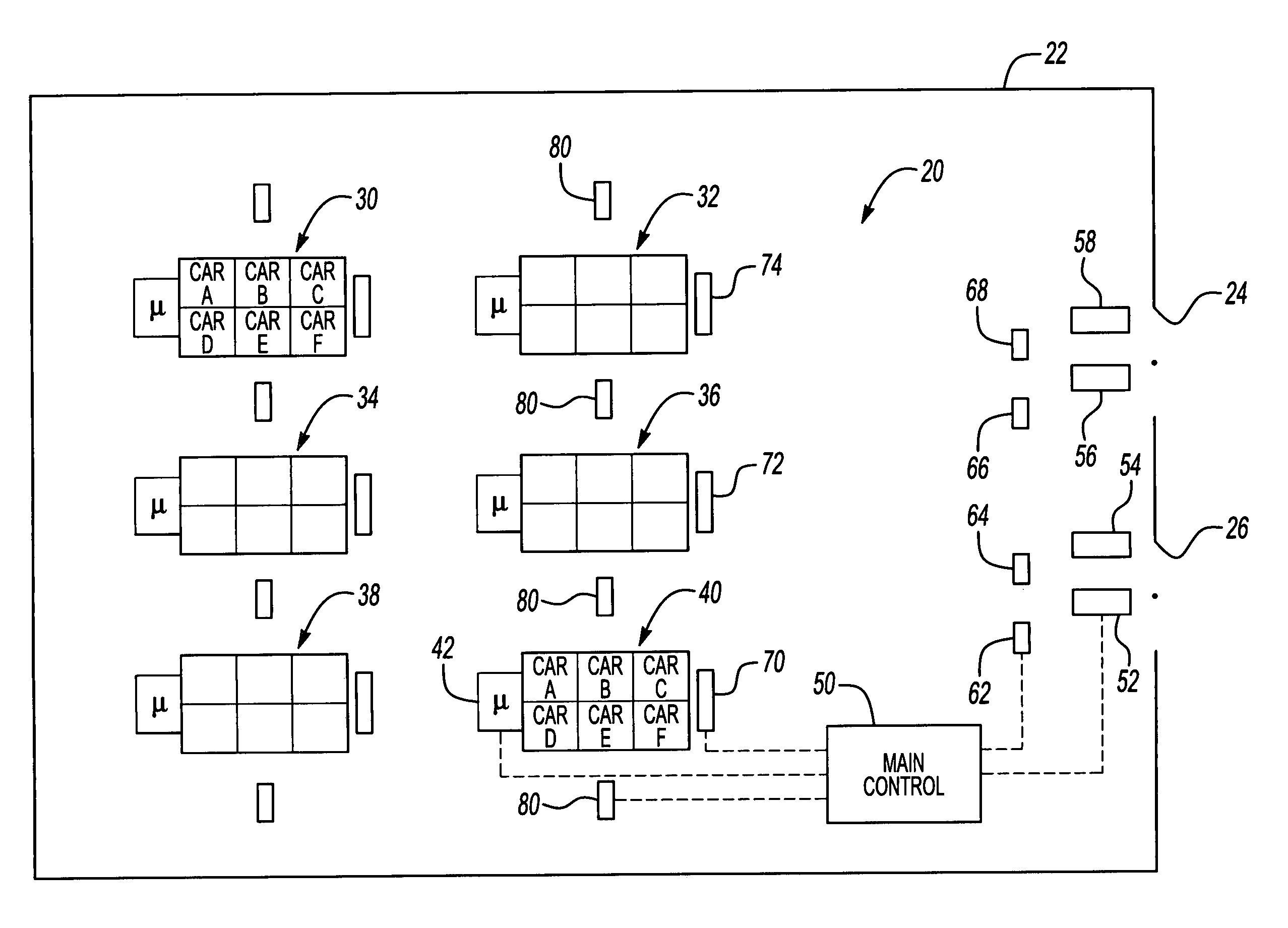
[0014]FIG. 1 schematically shows an elevator system 20 within a building 22. A plurality of access points 24 and 26 (i.e., doorways) allow individuals to enter a portion of the building space. The access points 24 and 26 are located remotely and, in this example, a considerable, fixed distance from a plurality of elevator groups 30, 32, 34, 36, 38 and 40.

[0015] The example elevator system 20 includes controlling elevator car movement and directing passenger traffic using destination entry techniques. The example system is particularly well suited to directing passengers to their assigned car even when there is a considerable amount of time between when the passenger's destination request is received by the system and when the passenger arrives in the vicinity of an appropriate elevator car.

[0016] Considering the elevator group 40 as an example, a plurality of cars A-F are included within the group. Known techniques for assigning particular cars to particular floor destinations are...


PUM


Abstract

An elevator system utilizes a destination entry control technique and delays indicating which car is assigned to a request to allow an individual to arrive near an elevator lobby. An elevator group assignment is made responsive to a destination request. An indication regarding the group assignment is provided to a passenger within a first time from the receipt of the request. A second indication regarding a car assigned to carry that passenger to the desired destination is provided at a second, later time from the request. Separating out the group assignment indication and the car assignment indication is accomplished in one example by providing separate interfaces at different locations within a building, for example. A disclosed example includes making the group assignment and car assignments at separate times corresponding to a difference in time between receipt of the initial request and the passenger's expected or actual arrival in the vicinity of the assigned elevator group.

Description

1. FIELD OF THE INVENTION [0001] This invention generally relates to elevator systems. More particularly, this invention relates to assigning cars in a destination entry system. 2. DESCRIPTION OF THE RELATED ART [0002] Elevator systems are in widespread use throughout the world. Various system configurations and strategies are known for controlling passenger traffic and efficiently operating an elevator system. [0003] Traditionally, hall call buttons allowed passengers to place a call to go up or down within a building and then to select a destination floor from a car operating panel located within an elevator car. While such arrangements are useful for many situations, larger buildings with more traffic volume have been shown to benefit from other control techniques. One example technique is known as destination entry. [0004] In a destination entry system a passenger provides an indication of a desired destination outside of an elevator car. Most destination entry systems include d...

Claims


Application Information

Patent Timeline
IPC IPC(8): B66B1/34B66B3/00
CPCB66B1/18
Inventor ZAHARIA, VLADCHRISTY, THERESAMANGINI, RICHARDSTANLEY, JANNAHSTRANIERI, PAULMONTAGUE, WADE
Owner OTIS ELEVATOR CO
Learn More