
Sliding door for a motor vehicle

a sliding door and motor vehicle technology, applied in the direction of door/window fittings, wing accessories, lock applications, etc., can solve the problems of considerable control engineering effort and major loss of operation ease, and achieve the effect of enhancing ease of operation

Inactive Publication Date: 2006-03-23
BROSE SCHLIESSSYSTEME GMBH & CO KG
View PDF18 Cites 19 Cited by
  • Summary
  • Abstract
  • Description
  • Claims
  • Application Information

AI Technical Summary

Benefits of technology

[0011] A primary object of this invention is to embody and develop the known sliding door for a motor vehicle such that the ease of operation is enhanced with simple means.
[0012] This object is achieved by a sliding door for a motor vehicle of the initially mentioned type by the engagement module, when the sliding door has been fixed in the opened position, being actuatable by a drive in a motorized manner. In this way, the engagement element can be released and the sliding door can then be moved in the closing direction.
[0013] What is important is the engagement module of the fixing arrangement being provided with the ability to be actuated by a motor. In this way, it is possible to reduce the actuation of the engagement module to the actuation of an electrical switch or to the actuation of a remote control. Actuation of the engagement module by the operator is thus associated with a minimum expenditure of force.
[0014] In one preferred configuration, it is provided that the closing principle known from the field of motor vehicle door locks with latch, ratchet and engagement element is also used for the fixing arrangement of the sliding door. This is advantageous, provided that the latch and ratchet can be easily designed such that lifting of the ratchet is possible with minimum expenditure of force. This leads to an advantageous design of the drive.
[0015] Furthermore, it should be emphasized that the engagement of the ratchet, and thus, blocking of the latch are ensured even in vigorous opening of the sliding door. The ratchet can be easily designed such that even with extremely high-speed rebound of the sliding door, an adequate engagement speed is ensured.

Problems solved by technology

This leads to a major loss of operating ease.
Aside from the fact that this approach can be applied solely to a sliding door which can be moved by a motor, it leads to considerable control engineering effort.

Method used


Image

  • Sliding door for a motor vehicle
  • Sliding door for a motor vehicle
  • Sliding door for a motor vehicle

Examples


Embodiment Construction

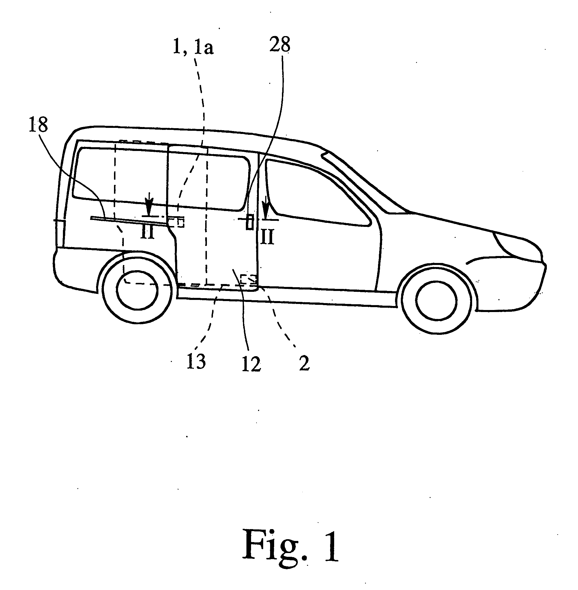
[0033]FIG. 1 shows a motor vehicle which is equipped with the sliding door in accordance with the invention. The sliding door can be slid into an opened and into a closed position, and thus, closes the loading and unloading opening of the motor vehicle. For this purpose, the sliding door is rail-guided, as is described in detail below. However, other designs can also be chosen for implementing the desired kinematics of motion of the sliding door.

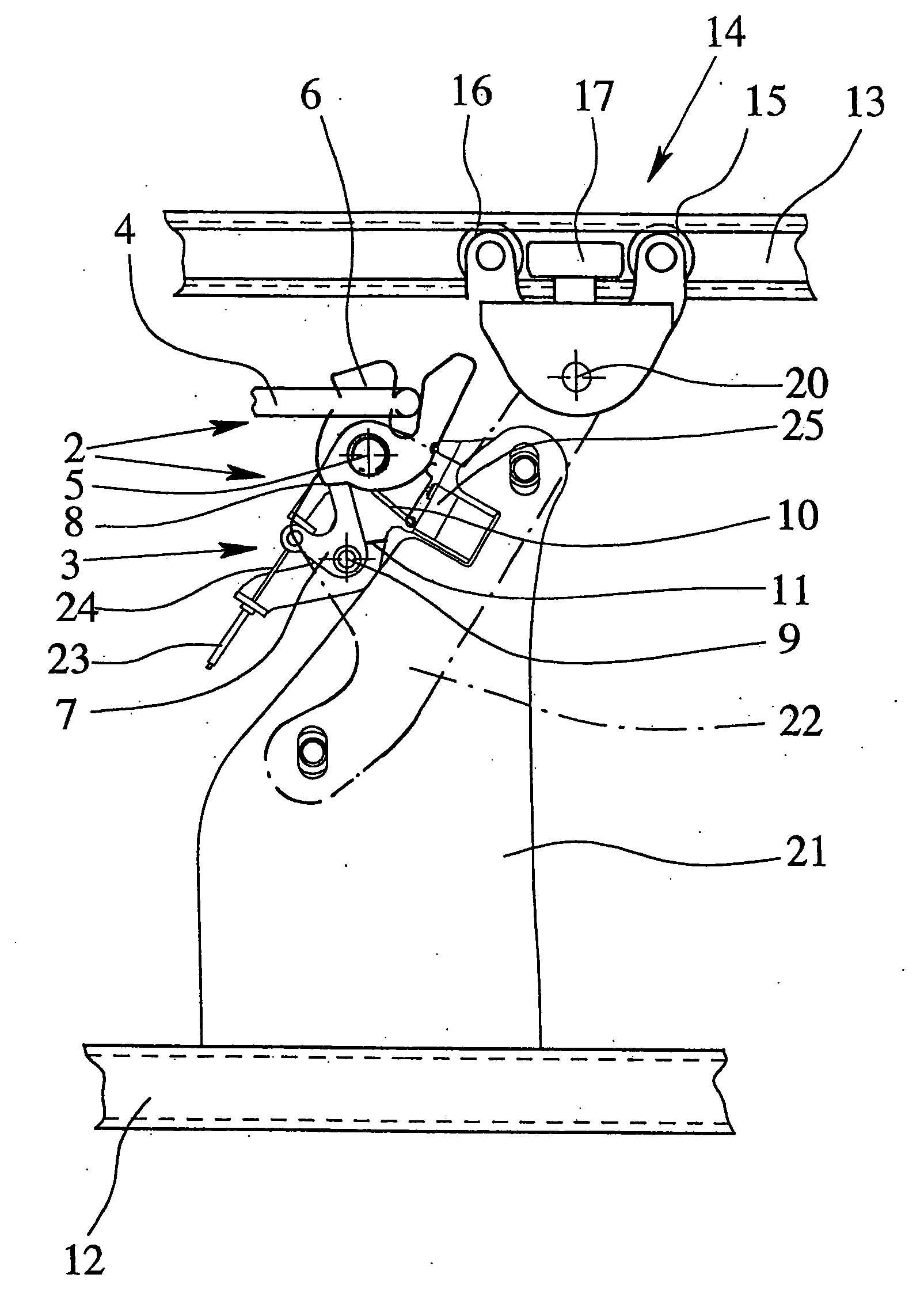
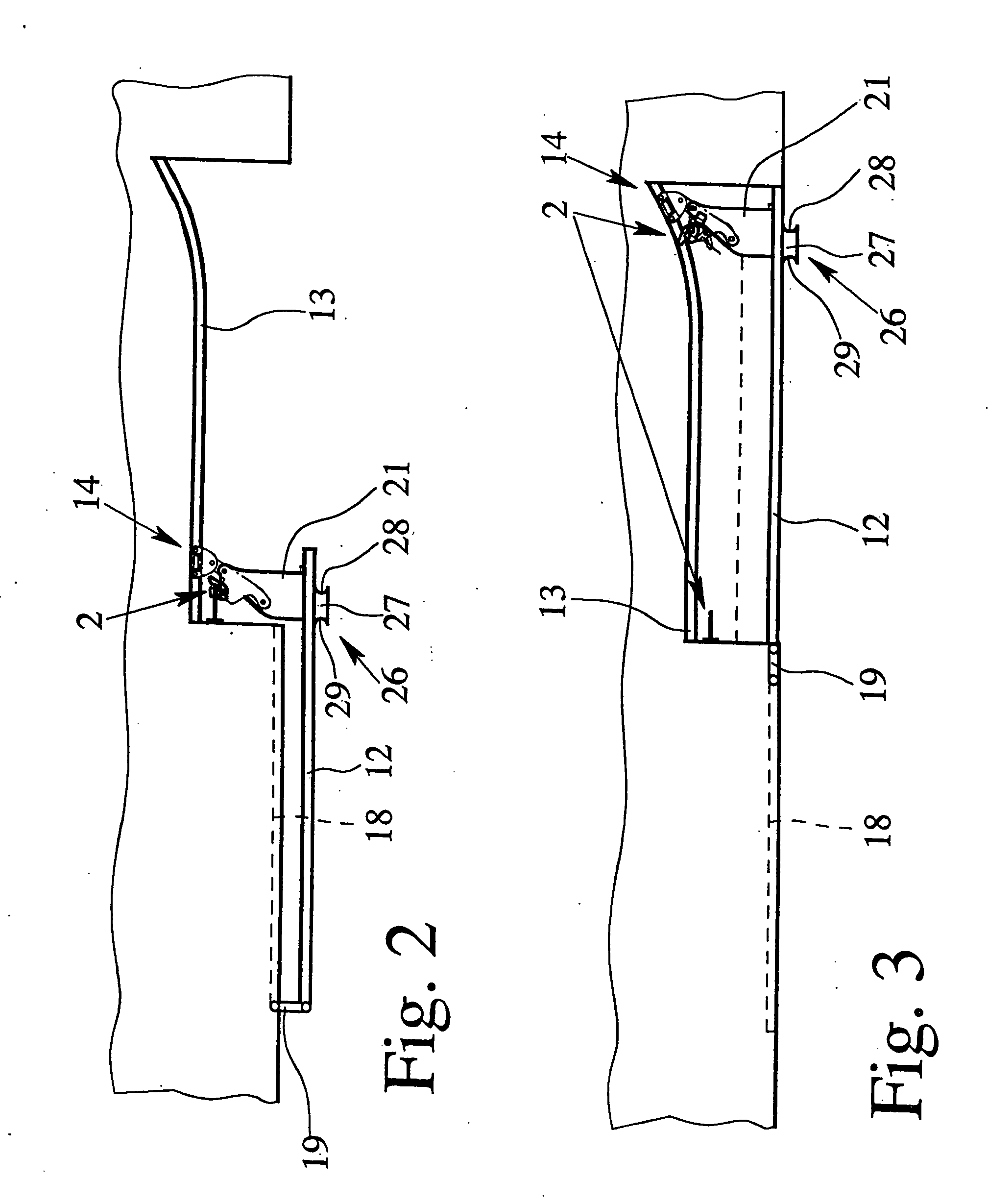
[0034] Generally, a sliding door has a motor vehicle lock arrangement 1 by which the sliding door can be fixed and locked in its closed position (FIG. 1, not shown in FIGS. 2, 3). However, it is important here that there is a fixing arrangement 2 with which the sliding door can be fixed in its opened position. The opened position of the sliding door is shown in FIG. 2, and the closed position in FIG. 3.

[0035] The fixing arrangement 2 has an engagement module 3, on the one hand, and an engagement element 4, on the other, the engagement modu...


PUM


Abstract

A sliding door for a motor vehicle, the sliding door being movable by a sliding motion into an opened and into a closed position, and having a fixing arrangement (2). The fixing arrangement (2) has an engagement module (3) and an engagement element (4), the engagement module (3) engaging the engagement element (4) when the sliding door is moved into the opened position and in this way fixing the sliding door in the opened position. It is proposed that the engagement module (3), when the sliding door has been fixed in the opened position, can be actuated by a drive in a motorized manner so that, in this way, the engagement element (4) is released and the sliding door can then be moved in the closing direction.

Description

BACKGROUND OF THE INVENTION [0001] 1. Field of Invention [0002] This invention relates to a sliding door for a motor vehicle, the sliding door being movable by a sliding motion into an opened and into a closed position, there being a fixing arrangement having an engagement module and an engagement element, the engagement module engaging the engagement element when the sliding door is moved into the opened position and in this way fixes the sliding door in the opened position. [0003] 2. Description of Related Art [0004] Here, the term “sliding door” encompasses all components which are necessary for the functionality of a sliding door. They include, in addition to the sliding component, also the corresponding frame which is provided in the motor vehicle body, guide rails which may be present, etc. The term “sliding door” is used below synonymously with the term “sliding component” whenever it promotes readability. [0005] Sliding doors have been used for a long time for delivery truck...

Claims


Application Information

Patent Timeline
IPC IPC(8): E05F11/00E05C17/60E05F15/60
CPCE05B63/143E05B65/0835E05B65/0858E05B81/14E05B85/26E05D13/04E05F15/60E05Y2201/22E05Y2201/246E05Y2201/434E05B79/20E05B83/40E05Y2900/531
Inventor BRAUN, THOMASBENDER, DANIELALANGFERMANN, MICHAELHACKLAENDER, RALFGAMPE, MICHAEL-MICHAELKOTHE, MARKUS
Owner BROSE SCHLIESSSYSTEME GMBH & CO KG
Learn More