
Helmet for displaying environmental images in critical environments

a technology for environmental images and helmets, applied in the direction of television systems, color televisions, garments, etc., can solve the problems of compromising the effectiveness and rapidness of intervention, the action of firefighters or law enforcement personnel in case of an accident is particularly risky for the injured, and the known system and device is limited in monitoring and rescue applications, so as to achieve a greater amount of information

Active Publication Date: 2006-03-09
DONATO GIUSEPPE
View PDF5 Cites 216 Cited by
  • Summary
  • Abstract
  • Description
  • Claims
  • Application Information

AI Technical Summary

Benefits of technology

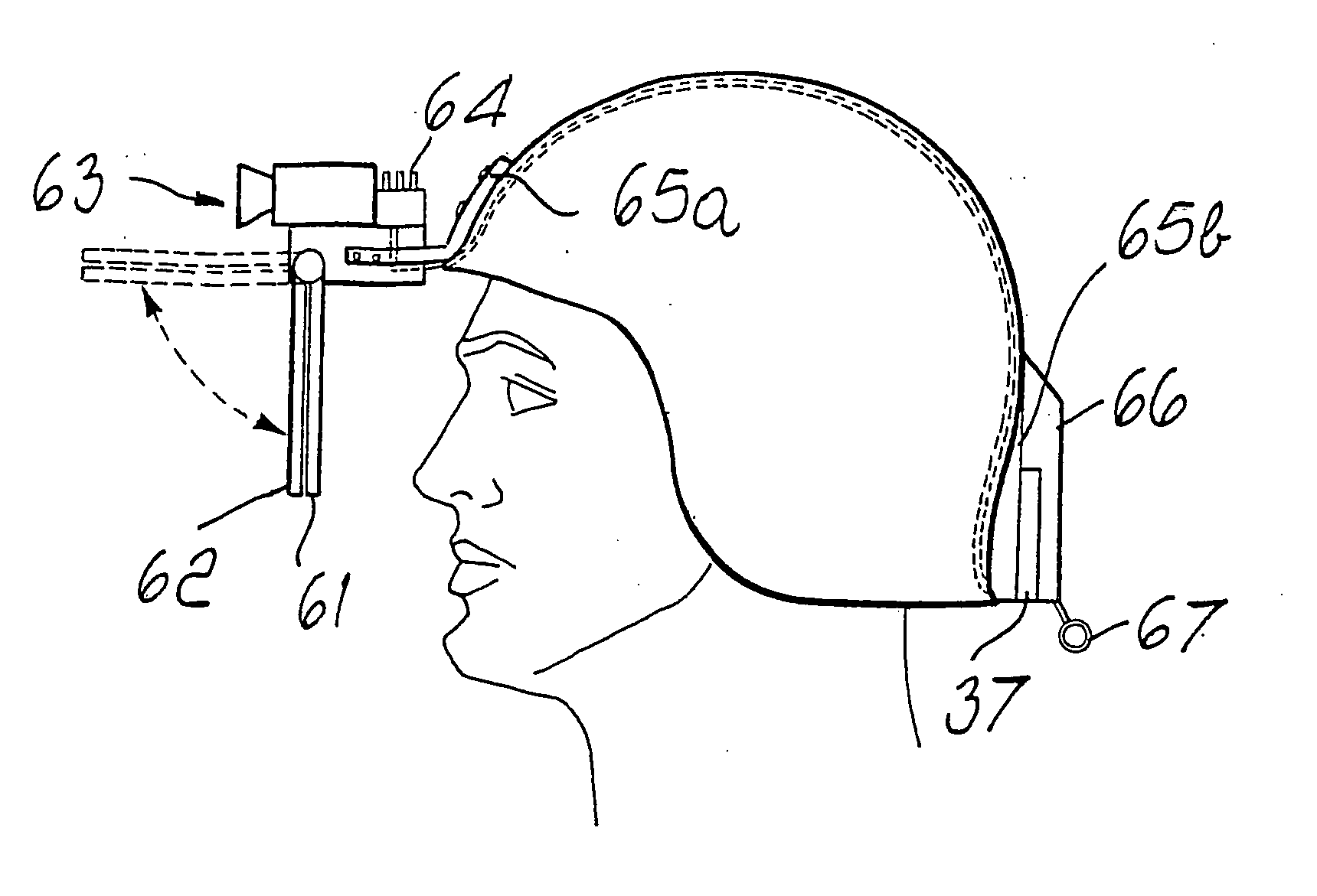
[0013] The aim of the present invention is to overcome the limitations described above by providing a helmet for surveillance of critical areas that is of the modular type and in which the components can be inserted in an integrated system that allows users to share a greater amount of information.
[0014] Within this aim, an object of the invention is to increase intervention efficiency in case of accident and to reduce the risks linked to said intervention operations.
[0015] Another object is to improve the quality of the picture displayed by the user in order to make the monitored situation more comprehensible.
[0016] Another object is to provide an anchoring system that is flexible and inexpensive, allowing use on existing helmets.

Problems solved by technology

In these critical areas, actions for intervention and rescue on the part of firefighters or law enforcement personnel in case of an accident are particularly risky for the injured people, for their rescuers and for all the people involved in the accident, since the escape routes are often difficult to detect.
The smoke of a fire, darkness or fog are the factors that most significantly compromise the effectiveness and swiftness of an intervention.
Known systems and devices are limited in monitoring and rescue applications in critical areas because they do not integrate information effectively.

Method used


Image

  • Helmet for displaying environmental images in critical environments
  • Helmet for displaying environmental images in critical environments
  • Helmet for displaying environmental images in critical environments

Examples


Embodiment Construction

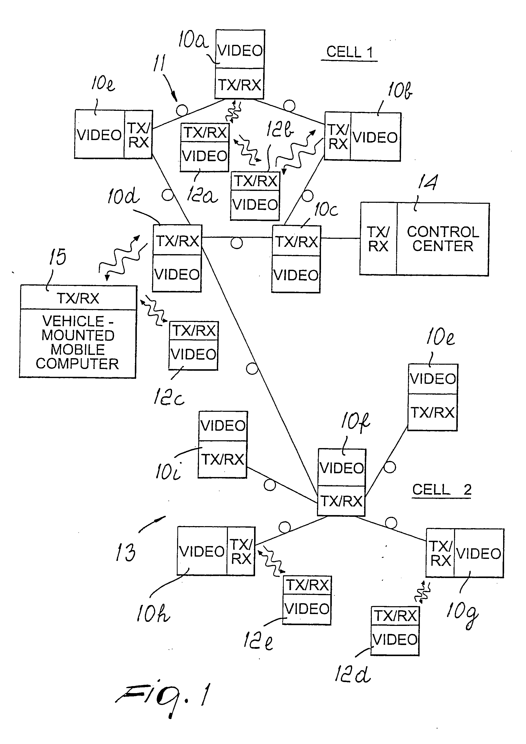
[0038] With reference to FIG. 1, the surveillance system comprises a number of fixed stations 10a-101 and a number of mobile stations 12a-12e.

[0039] The fixed stations are inserted in a network, preferably of the fiber-optic type with known layouts such as a ring 11 or a star 13 or linear layouts, and are mutually connected according to a cluster-type layout, in which combinations of the layouts 11 and 13 and linear layouts are repeated according to the surveillance requirements to be met.

[0040] Said fiber-optic system can be connected to a control center 14, which has processing and supervision functions, and to a mobile processing center 15, which is typically mounted on a vehicle. Each station can communicate bidirectionally with any other fixed or mobile station.

[0041] The mobile stations are of different types, and as will become better apparent hereinafter, they can be mounted on a helmet, on vehicles such as cars, trucks, aircraft, on autonomous self-propelled robots, or o...


PUM


Abstract

A helmet for displaying environmental images in critical environments, comprising at least one video camera and means for displaying environmental images, characterized in that it comprises a supporting structure that can be anchored to said helmet in order to support said at least one video camera and said display means, said supporting structure comprising a front adapter that can be coupled to a front edge of said helmet, a rear adapter that can be coupled to a rear edge of said helmet, and a connecting element for mutually connecting said front adapter and said rear adapter.

Description

TECHNICAL FIELD [0001] The present invention relates to a helmet for displaying environmental images in critical environments, particularly areas at risk of accident or in which an accident has occurred such as tunnels, subways, wooded areas, refineries, nuclear facilities, shopping centers and in general sites with high concentrations of people. BACKGROUND ART [0002] In these critical areas, actions for intervention and rescue on the part of firefighters or law enforcement personnel in case of an accident are particularly risky for the injured people, for their rescuers and for all the people involved in the accident, since the escape routes are often difficult to detect. The smoke of a fire, darkness or fog are the factors that most significantly compromise the effectiveness and swiftness of an intervention. [0003] These factors can themselves be the cause of an accident or can worsen one, since even in the absence of an accident, in certain critical areas (such as for example tun...

Claims


Application Information

Patent Timeline
IPC IPC(8): A42B1/24G02B27/01G08B13/196H04N7/18
CPCA42B3/042G02B27/0149G02B27/0176G08B13/19621G08B13/1963H04N7/181G08B13/19634G08B13/1965G08B13/19684G08B13/19695G08B13/19632
Inventor DONATO, GIUSEPPE
Owner DONATO GIUSEPPE
Learn More