
Inkjet recording apparatus

a recording apparatus and inkjet technology, applied in the direction of printing, other printing apparatus, etc., can solve the problems of increasing the time required for image recording, deteriorating image quality, and significant so as to reduce the deterioration of image quality due to uneven recording and shorten the recording time

Active Publication Date: 2006-03-02
KONICA MINOLTA INC
View PDF8 Cites 19 Cited by
  • Summary
  • Abstract
  • Description
  • Claims
  • Application Information

AI Technical Summary

Benefits of technology

[0011] The present invention was made in order to solve the problems as described above. It is an object of the invention to provide an inkjet recording apparatus according to which a line head type recording apparatus provides an image recording with a resolution equal to or higher than a nozzle interval so that the deterioration of image quality due to uneven recording can be reduced and the recording time can be shortened.

Problems solved by technology

This causes a case in which, even when the respective nozzles jet the same amount of ink, the stripe uneven recording 51 may be frequently generated in a direction along which the recording medium 52 is conveyed, causing a significant deterioration of image quality.
This has caused a problem of an increased time required for the image recording that is remarkable when the plurality of recording heads 53 are used because the conveyance amount L for one scanning is increased and an image recording to next recording medium cannot be started until one recording to a current recording medium is completed by performing a predetermined number of scannings.
Thus, ink jetted from the second recording head 53 is performed within a time in which ink jetted from the first recording head 53 is not sufficiently absorbed by the recording medium 52, causing a problem in which a plurality of inks jetted from different recording heads have a bleeding, causing the deterioration of the image quality.

Method used


Image

  • Inkjet recording apparatus
  • Inkjet recording apparatus
  • Inkjet recording apparatus

Examples


embodiment 1

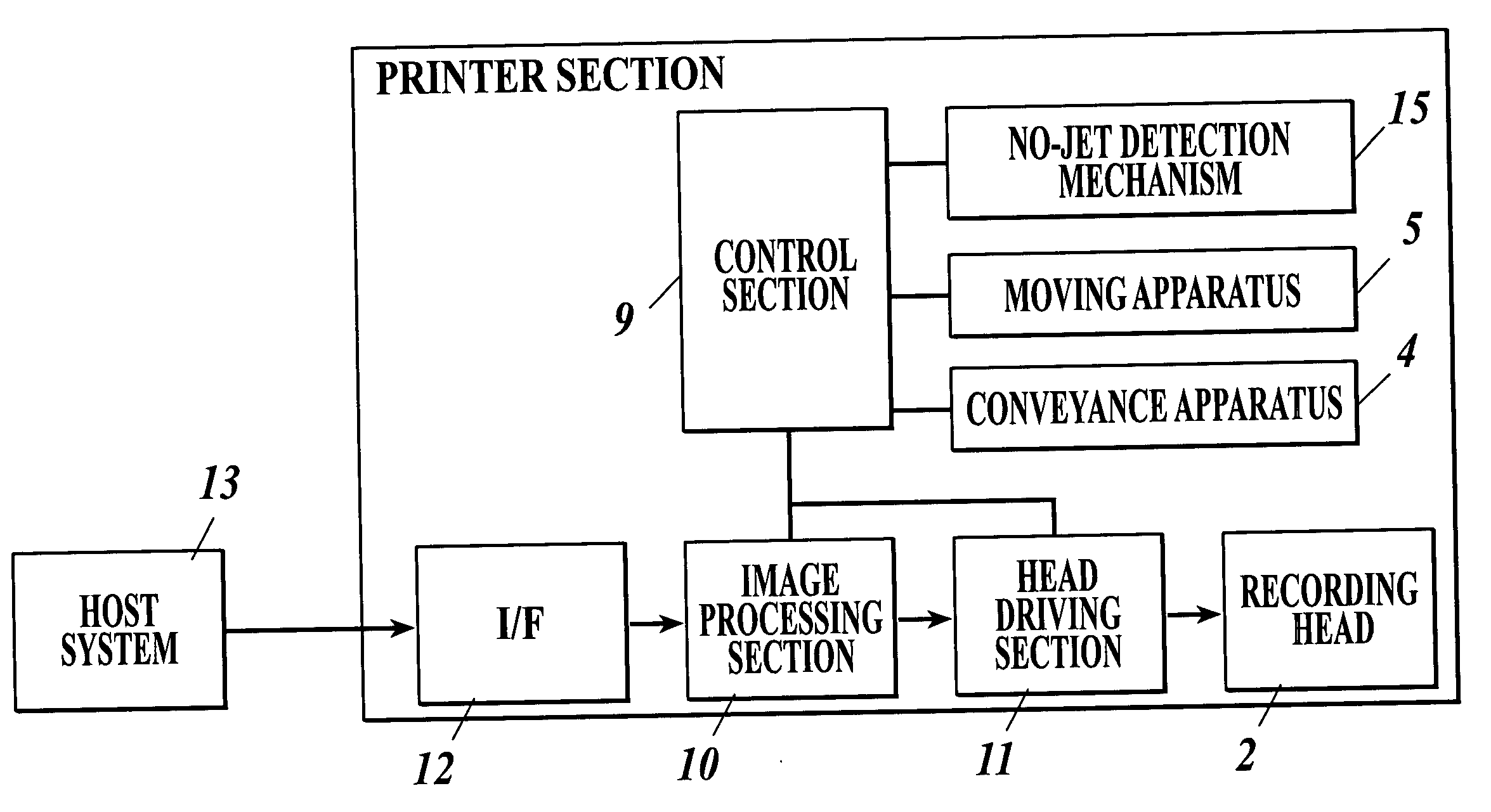
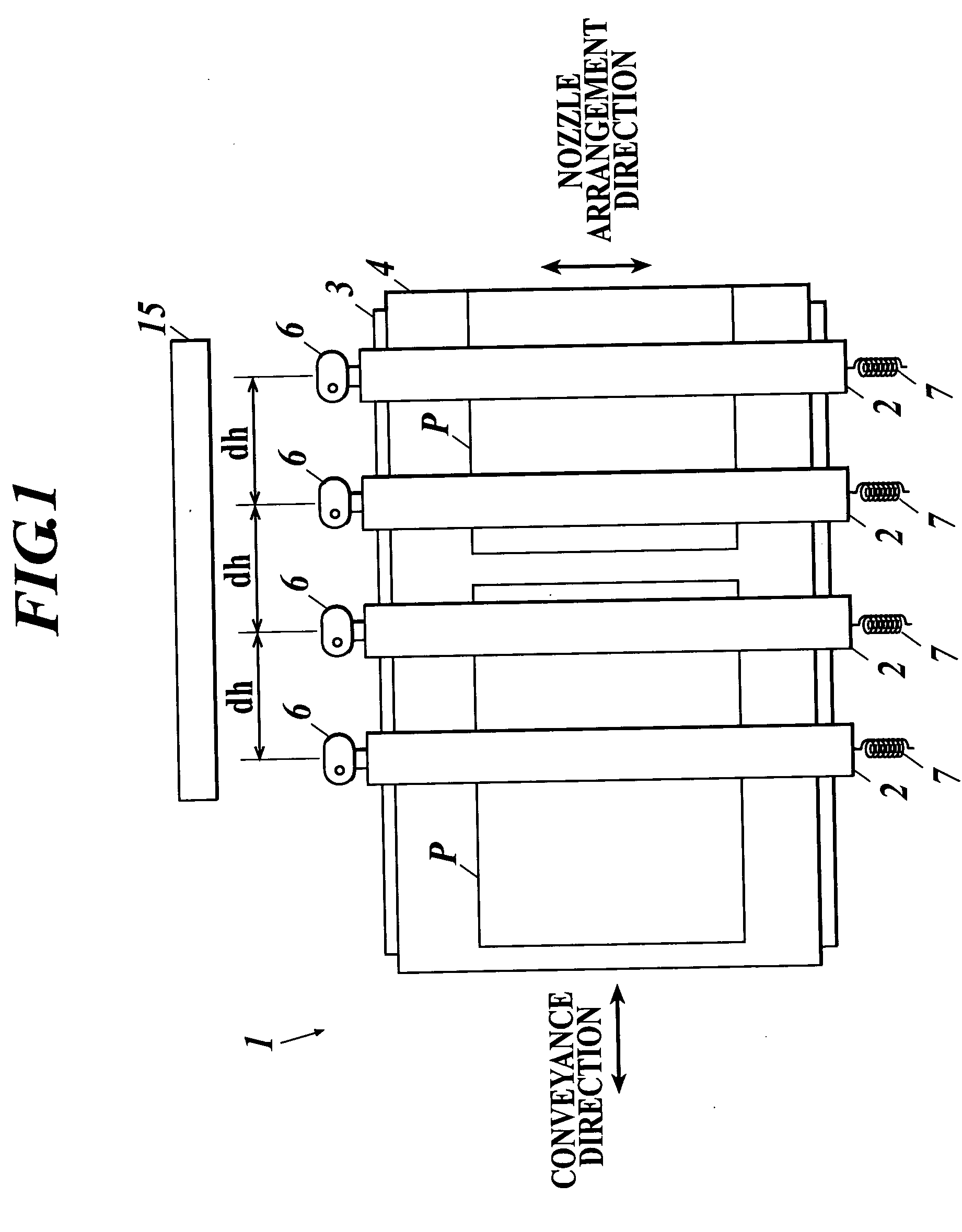
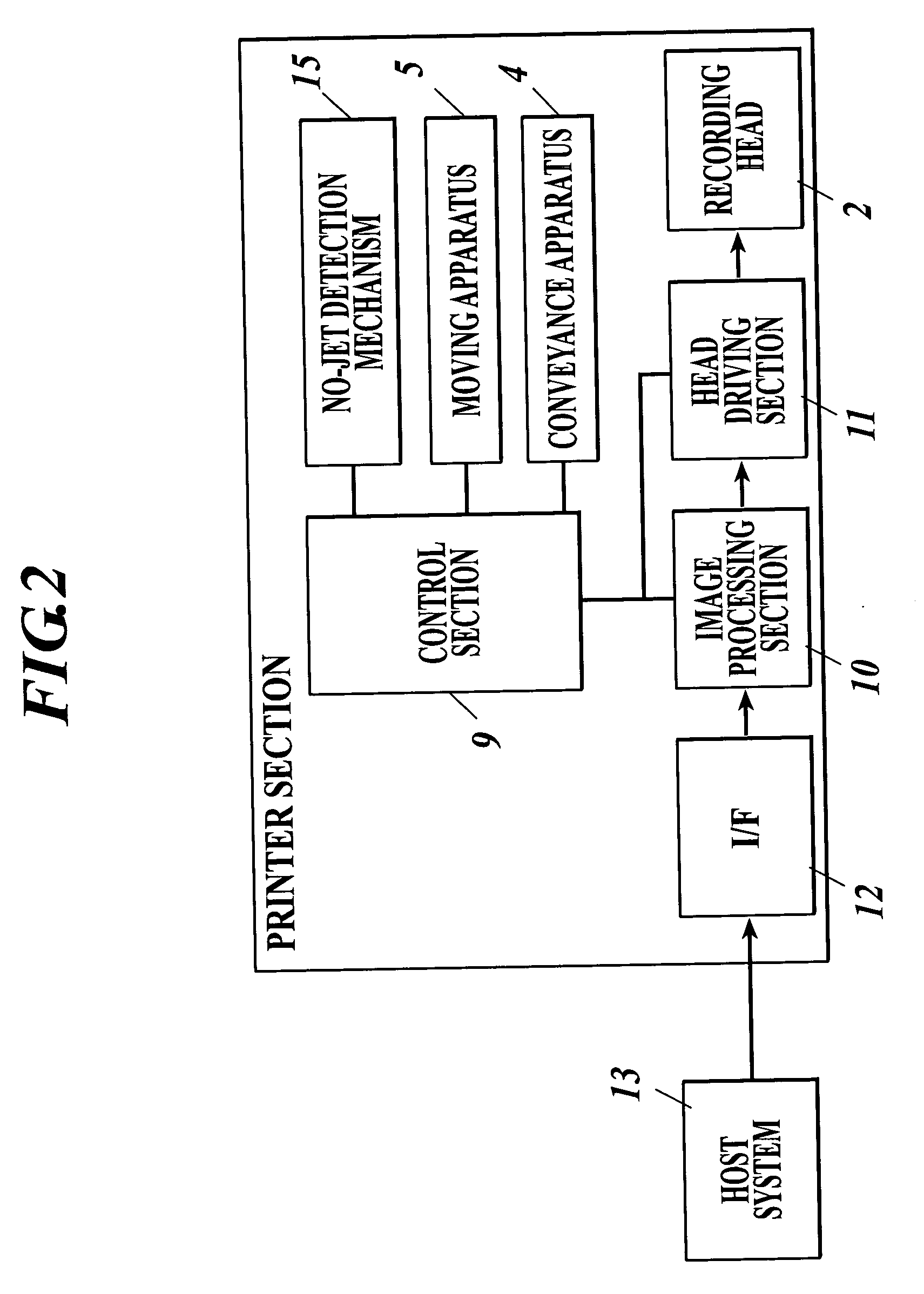
[0062]FIG. 1 is a schematic view of an inkjet recording apparatus 1 according to this embodiment. The inkjet recording apparatus 1 is the line head type inkjet recording apparatus 1 for forming an image using a line type recording head 2 orthogonal to the conveyance direction of the recording medium P.

[0063] This inkjet recording apparatus 1 includes a platen 3 for supporting, from the lower part, the recording medium P. The platen 3 includes a conveyance apparatus 4 consisting of a conveyance belt or the like for conveying the recording medium P in an intermittent manner. At a position that is above the platen 3 and that is above the recording medium P, there are provided a plurality of recording heads 2 for jetting the respective colors of inks (Y: yellow, M: magenta, C: cyan, K: black) in a direction orthogonal to the conveyance direction of the recording medium P. The respective recording heads 2 are provided so as to have a predetermined interval “dh” thereamong in the conveya...

embodiment 2

[0106] Next, Embodiment 2 according to the present invention is described. An inkjet recording apparatus of this embodiment has substantially the same structure as that of the inkjet recording apparatus 1 of Embodiment 1 except for a process for performing an image recording. Specifically, the difference is that Embodiment 1 causes the dot thinning-out in the conveyance direction while Embodiment 2 controls each component so that the dot thinning-out is not performed in the conveyance direction and the nozzle arrangement direction and the interleave 3 is provided to record an image in a predetermined region by three scanning operations so that the recording is performed with a resolution equal to or higher than the nozzle interval of the recording head 2.

[0107] The following section describes the respective control configurations.

[0108] The control section 9 controls the moving apparatus 5 so that, whenever the conveyance direction of the recording medium P is switched, the record...

embodiment 3

[0119] Next, Embodiment 3 according to the present invention is described. An inkjet recording apparatus of Embodiment 3 has substantially the same structure as the inkjet recording apparatus 1 of Embodiment 1 except for a process for performing an image recording. As in Embodiment 2, the inkjet recording apparatus of Embodiment 3 is configured to provide an image recording so that dot thinning-out is not provided in the conveyance direction and the nozzle arrangement direction but the interleave 3 is provided. However, Embodiment 3 is different from Embodiment 2 only in that each component is controlled so that, at a position in the vicinity of a position at which the conveyance direction of the recording medium P is switched, the dot thinning-out is provided in the conveyance direction. Thus, regions other than the above position in the vicinity of the switching position are recorded by three scannings and the above position in the vicinity of the switching position is recorded by...


PUM


Abstract

An inkjet recording apparatus including: a line head type recording head having nozzles for jetting ink to a recording medium; a moving apparatus for moving the recording head relative to the medium in a nozzle arrangement direction; a conveyance apparatus for conveying the medium reciprocally, relative to the recording head in a direction orthogonal to the nozzle arrangement direction; a head driving section for controlling the recording head so that the recording head jets ink based on inputted image information; and a control section for controlling the conveyance apparatus so that the amount of the frontward movement of the medium in an outward route is larger than the amount of the backward movement in a homeward route and for controlling the moving apparatus, when the conveyance direction is switched, so that the recording head is moved relative to the medium in the nozzle arrangement direction.

Description

BACKGROUND OF THE INVENTION [0001] 1. Field of the Invention [0002] The present invention relates to an inkjet recording apparatus. In particular, the present invention relates to a line head type inkjet recording apparatus. [0003] 2. Description of Related Art [0004] Generally, among inkjet recording apparatuses, there are for example those of the serial head type in which a recording head is moved on a recording medium in a reciprocating manner so that the recording medium is conveyed in a direction orthogonal to a scanning direction of the recording head to form an image or those of the line head type in which a recording head fixed to have a nozzle row extending along the width of a recording medium so that the recording medium is conveyed in a direction perpendicular to the direction of the nozzle row to form an image. [0005] In the line head type inkjet recording apparatus 50, the position or direction of the nozzles of the recording head 53 is dislocated to cause, as shown in...

Claims


Application Information

Patent Timeline
Patent Type & Authority Applications(United States)
IPC IPC(8): B41J29/38
CPCB41J29/393
Inventor TSUTSUMI, TAKASHISUGAYA, TOYOAKINAGAI, MASARU
Owner KONICA MINOLTA INC
Learn More