
Medical skin applicator apparatus

Active Publication Date: 2006-02-23
KPR U S LLC
View PDF69 Cites 177 Cited by
  • Summary
  • Abstract
  • Description
  • Claims
  • Application Information

AI Technical Summary

Benefits of technology

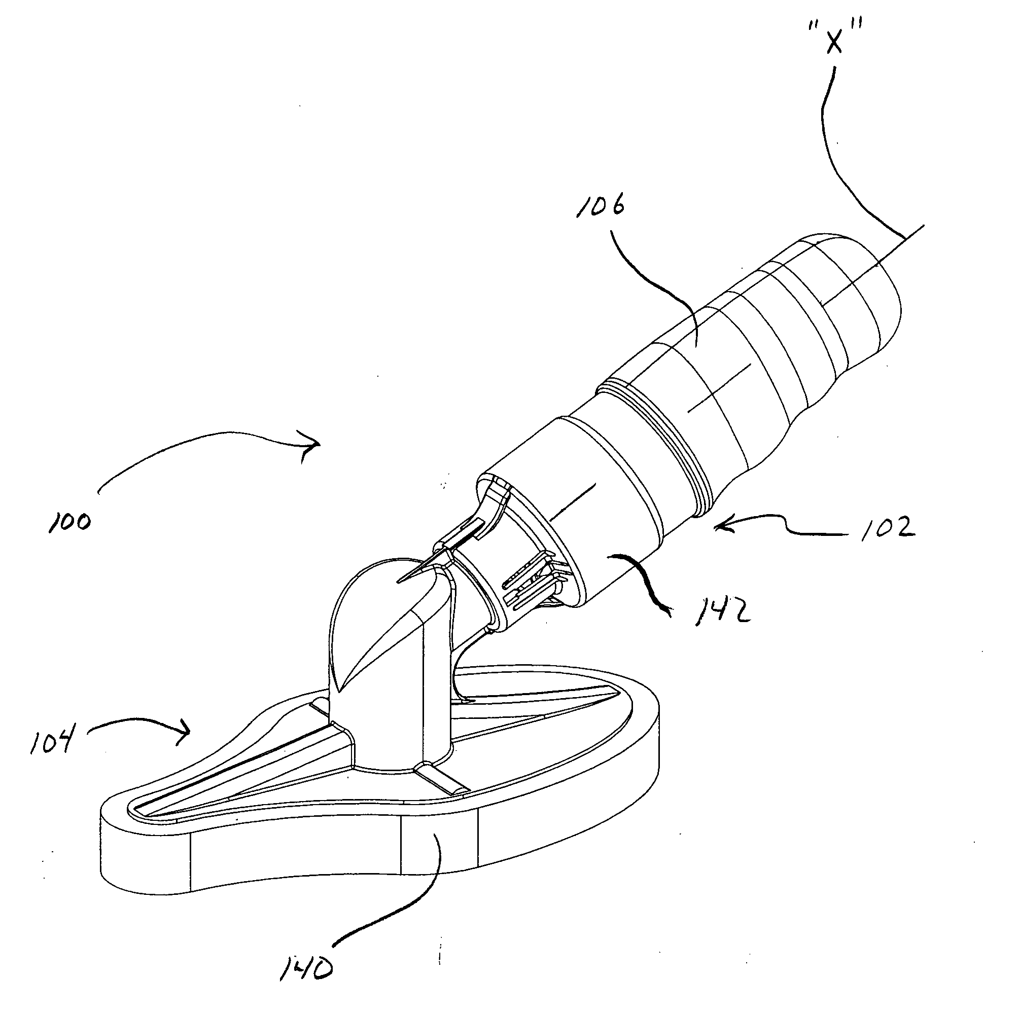
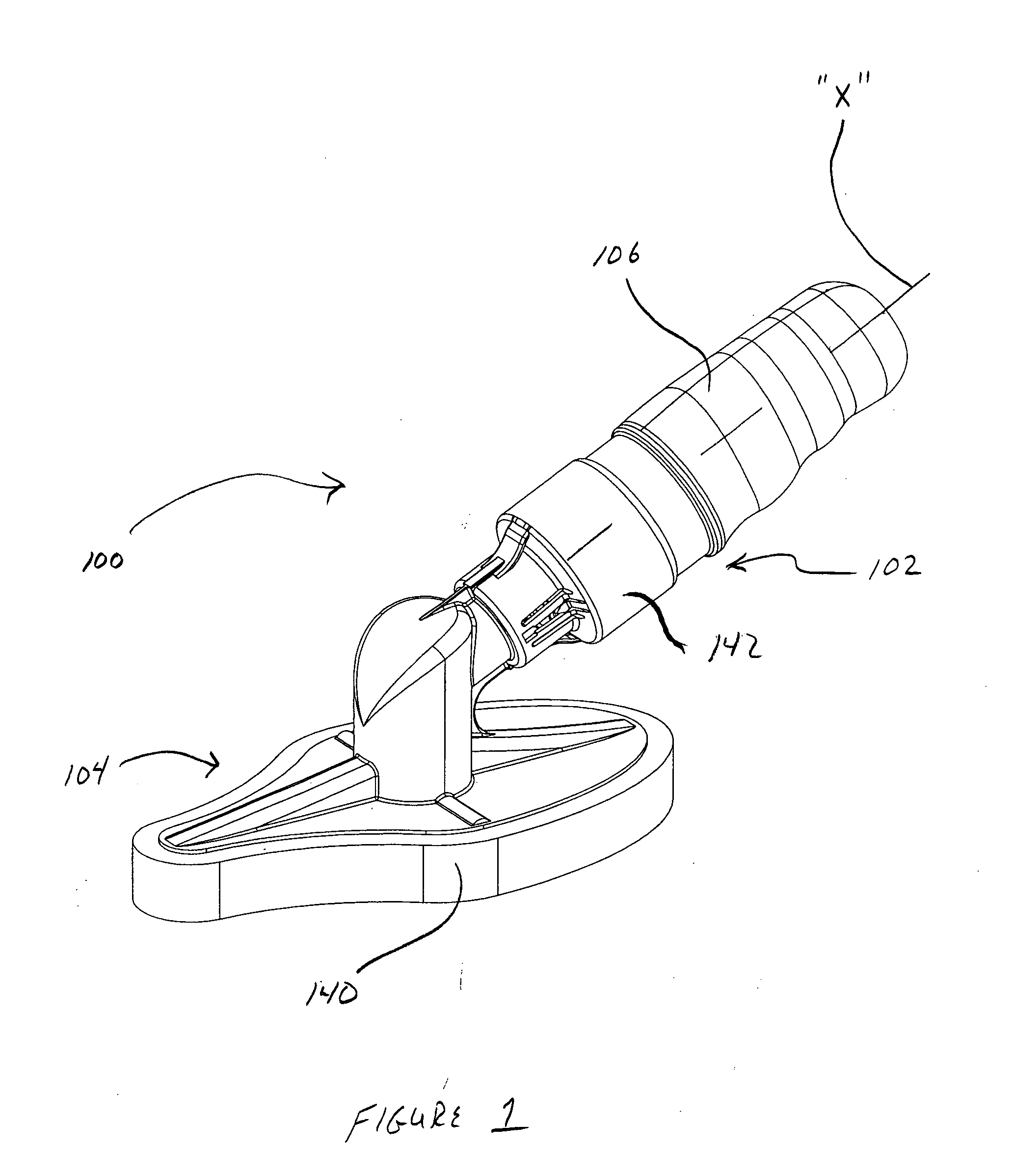
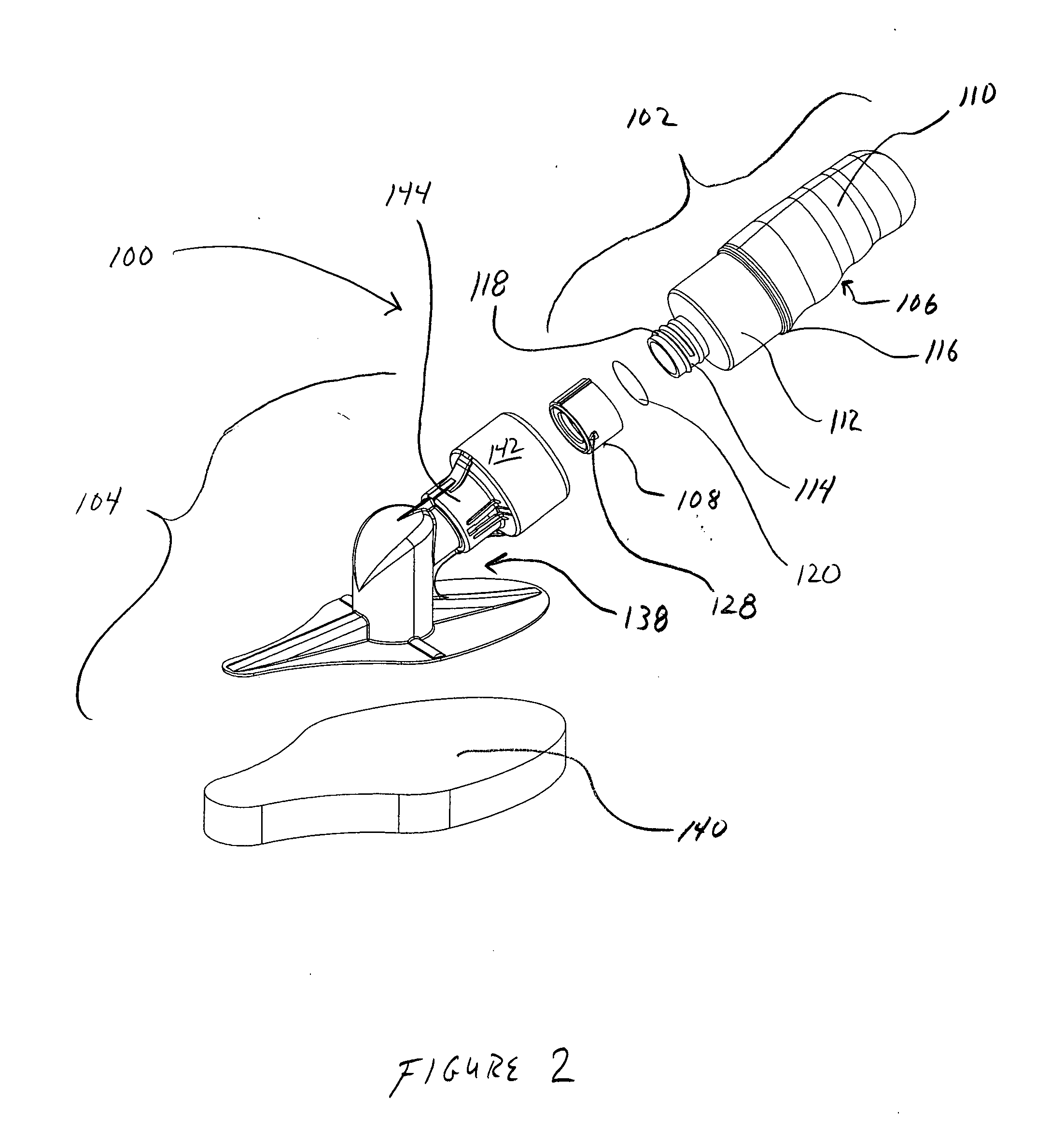
[0023] The applicator frame preferably includes an enlarged opening extending through a lower surface thereof and in communication with the conduit. The opening conveys fluid to the absorbent member. A supplemental channel may be adjacent the enlarged opening and in communication with the conduit. The supplemental channel facilitates dispensing of the medical agent. Preferably, first and second supplemental channels are adjacent forward and rear ends of the applicator frame and in communication with the conduit for facilitating dispensing of the medical fluid. The first and / or second channels may serve as vents for release of air captured within the absorbent member.

Problems solved by technology

However, numerous problems are encountered with applicators of this type.
Fracture of the glass ampoule generates shards within the applicator that may pose risks to a patient.
However, there still exists a possibility of introducing these shards into the fluid pathway, which poses an unacceptable and unnecessary risk to the patient.
Another drawback of the above mentioned devices is the permeation of certain gases through the seals of bottles as well as the plastic of the bottle.
The caps therefore become the weakest part of these systems and oftentimes leak due to inconsistent sealings (PET / foil) or due to cap loosening due to the pressure imparted during the EO sterilization process.
The result is a sharp, uneven and irregular top surface to the container, which is problematic when a seal is applied to the non-uniform surface and an irregular seal is formed.
The loosening of the cap is a common failure and oftentimes results in leakage of the bottle contents—especially when the system is pressurized or is required to remain in storage for long periods prior to use.
Finally current devices suffer from control of the contained fluid due to their design.
Fluids of higher viscosity do not readily flow out of standard ampule designs when inverted.
Inevitably these lower viscosity fluids result in loss of fluid control once dispensed to the patient's skin which poses an unnecessary risk of fire due to the associated pooling of alcohol within surgical drapes.
These devices suffer an inability of the fluid to migrate to the sponge dispensing means.

Method used


Image

  • Medical skin applicator apparatus
  • Medical skin applicator apparatus
  • Medical skin applicator apparatus

Examples


Embodiment Construction

[0088] The exemplary embodiments of the medical skin applicator apparatus and use(s) thereof are discussed in terms of medical skin applicators employed during medical procedures that involve application of sterilizing fluids, gels or agents to the skin of a body for preparation, treatment, etc. The skin applicator apparatus is advantageously configured to facilitate fluid communication of the sterilizing fluids with a skin contacting member or dispensing member of the skin applicator apparatus thereby enabling preparation and treatment of a skin surface of a patient. It is envisioned that the skin applicator apparatus may be employed in a range of medical procedures, such as, for example, surgical, diagnostic and related treatments of diseases and body ailments of a subject. It is further envisioned that the principles relating to the skin applicator apparatus disclosed include application of various agents to a body, such as, for example, medications and other fluids.

[0089] In th...


PUM


Abstract

A medical skin applicator apparatus includes a fluid housing having a fluid chamber for storing a medical agent and an applicator coupled to the housing. The fluid housing has a penetrable wall to permit access to the fluid chamber and release of the medical agent therefrom. The applicator includes an applicator surface for applying the medical agent to a patient. The applicator has a penetrating member adapted to penetrate the penetrable wall of the fluid housing upon achieving a predetermined coupled relation of the fluid housing and the applicator, to thereby permit the medical agent to be dispensed from the fluid chamber and applied to the patient with the applicator surface.

Description

CROSS REFERENCE TO RELATED APPLICATIONS [0001] This application claims the benefit of provisional application Ser. No. 60 / 599,927, entitled “Skin Applicator”, filed Aug. 9, 2004, and provisional application Ser. No. 60 / 614,503, entitled “Skin Applicator”, filed Sep. 30, 2004, and provisional application Ser. No. 60 / 637,182, entitled “Skin Applicator”, filed Dec. 22, 2004, the entire contents of each of these provisional applications being incorporated herein by reference.BACKGROUND [0002] 1. Technical Field [0003] The present disclosure relates generally to medical skin applicators, and more particularly, to a skin applicator apparatus adapted to uniformally and consistently dispense sterilizing fluid to a skin surface of a patient. [0004] 2. Description of the Related Art [0005] Many medical procedures involve application of medicines, sterilizing fluids, antiseptics, gels, agents or other materials to portions of the body, such as the skin, for preparation, treatment, etc. Such me...

Claims


Application Information

Patent Timeline
IPC IPC(8): B43K5/14B43M11/06
CPCA61M35/003A61M5/3007A61M2037/0007A61M2210/04
Inventor CABLE, FRANK A. JR.TAUER, MARKFETTERROLL, ANDREW
Owner KPR U S LLC
Learn More