Magnetic head heating element in a disk drive
a heating element and disk drive technology, applied in the direction of mounting the head within the housing, maintaining the alignment of the head carrier, instruments, etc., can solve the problems of shortening the lifetime of the magnetic disk device, and affecting the operation of the disk driv
- Summary
- Abstract
- Description
- Claims
- Application Information
AI Technical Summary
Benefits of technology
Problems solved by technology
Method used
Image
Examples
embodiment 1
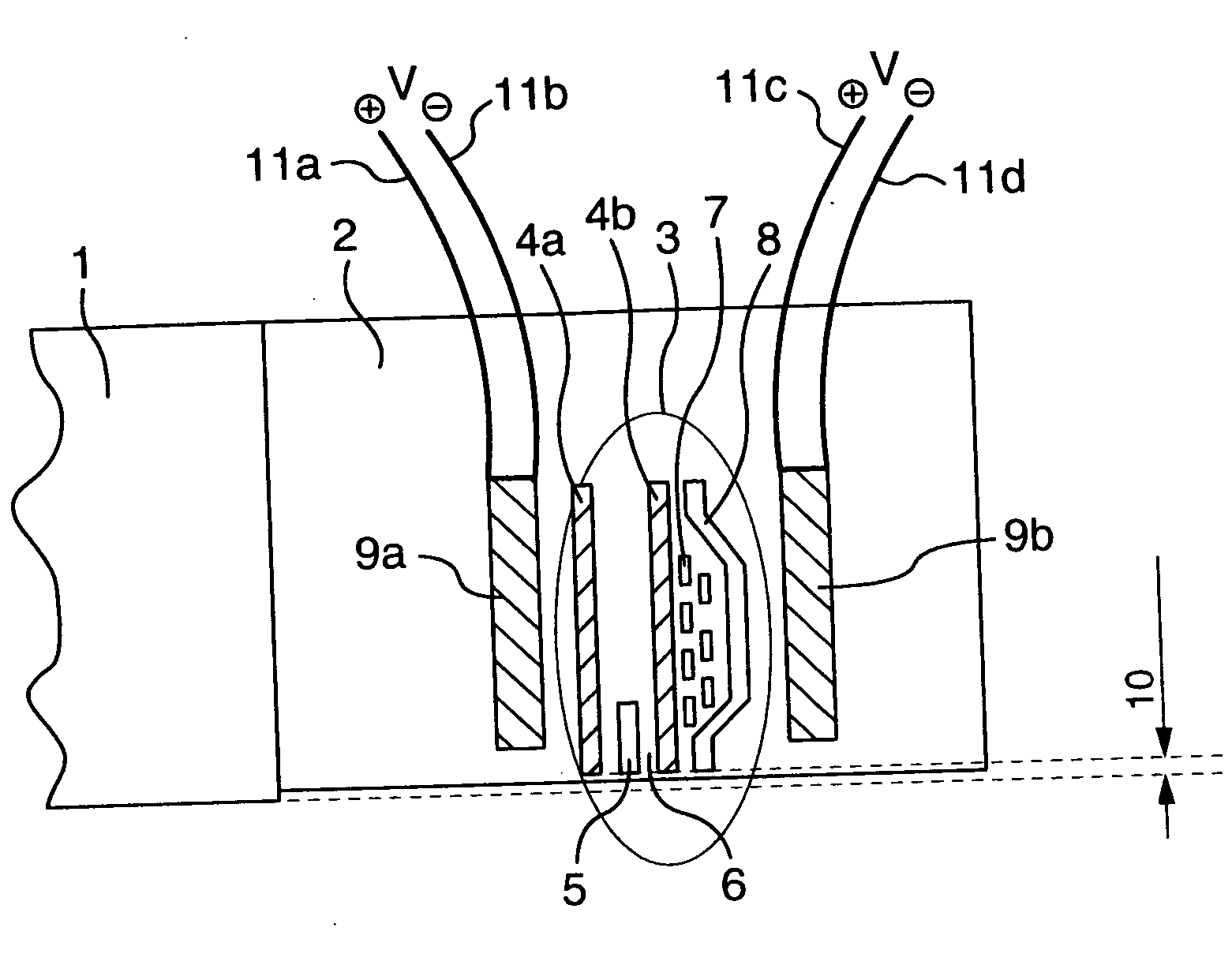
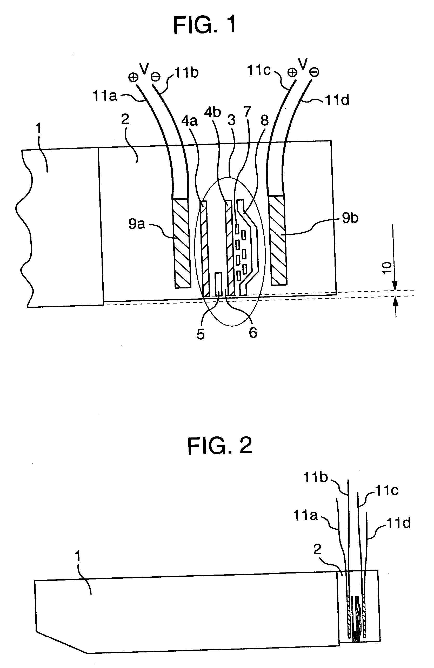
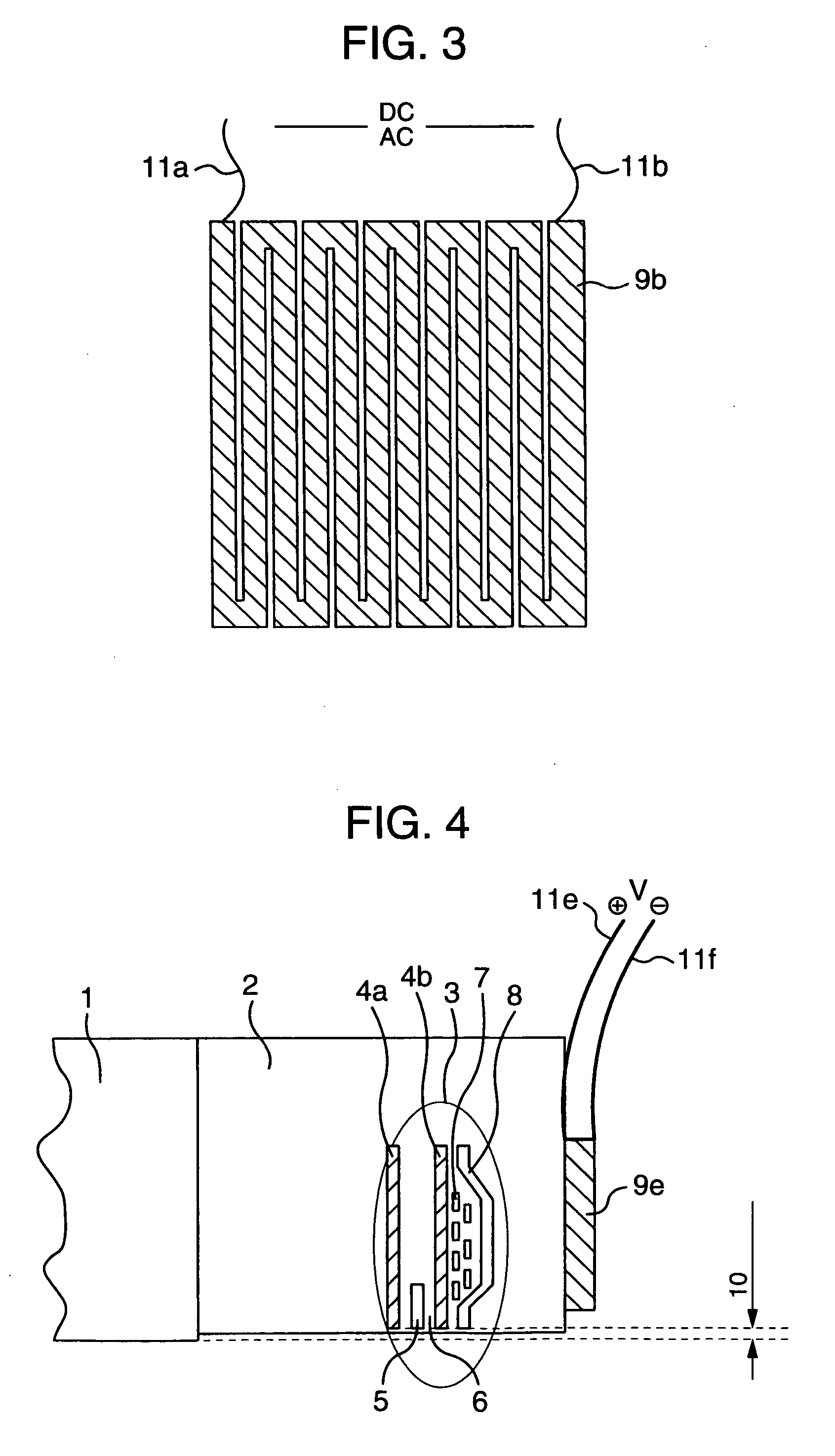
[0038] The following will discuss embodiments of the present invention referring to the drawings. Referring to FIGS. 1 to 4, Embodiment 1 of a magnetic head slider according to the present invention will be discussed by taking a magnetoresistance type head as an example. FIG. 1 is an enlarged side view showing a magnetic head, and FIG. 2 is a side view showing the magnetic head slider.
[0039] Further, FIG. 22 schematically shows the configuration of a magnetic disk device according to the present invention. FIG. 22 is a perspective view showing a magnetic head device 100 having a magnetic head slider 104, which will be discussed below.
[0040] In a magnetic disk device 101, a hub 103 is driven and rotated around a rotary axis 102 by a spindle motor (not shown). A plurality of rotating magnetic disks 101 is attached to the hub 103 inside a casing (case) 111. The slider 104 positioned on a surface of the disk floats via a small gap due to the rotation of the magnetic disk 101 and is sup...
embodiment 2
[0058] Referring to FIGS. 10 to 12, a magnetic head slider of the present invention will be discussed. FIG. 10 is a side view showing a magnetic head part having a temperature sensor bonded to the rear of the head. FIG. 11 is a side view showing the magnetic head part having a temperature sensor bonded to the back of the head. FIG. 12 is a drawing taken from the back of the magnetic head part having temperature sensors bonded to the side of the head.
[0059] The configuration of the present embodiment will be discussed. According to the present embodiment, in the configuration of Embodiment 1 of the present invention, a temperature sensor 14a is further provided on the rear of the magnetic head and a control circuit 15 is provided which uses the temperature sensor to control voltage or current applied to the electric conducting films so as to control a temperature of the head element part 3.
[0060] Besides, in the present embodiment, as shown in FIG. 11, a temperature sensor 14b may ...
embodiment 3
[0062] Referring to FIGS. 13 and 14, a magnetic head slider of the present invention will he discussed. FIG. 13 is a side view showing the magnetic head part having electric conducting films connected to a load / unload (L / UL) control circuit. FIG. 14 is a flowchart showing load / unload control.
[0063] The configuration of the present embodiment will be discussed below. The present embodiment is identical to Embodiment 1 of the present invention in configuration of a head. The head is configured such that the head element 3 has a machining step (PTR) when current is not applied to the head element 3 or the electric conducting films 9a and 9b. Further, the present embodiment has the load / unload mechanism, and application of voltage or current to the electric conducting films is controlled by an operation command of load / unload control of the magnetic head slider 1. To be specific, a control circuit 16 is provided which reduces voltage or current applied to the electric conducting films ...
PUM
| Property | Measurement | Unit |
|---|---|---|
| flying height | aaaaa | aaaaa |
| temperature | aaaaa | aaaaa |
| length | aaaaa | aaaaa |
Abstract
Description
Claims
Application Information
 - R&D
- Intellectual Property
- Life Sciences
- Materials
- Tech Scout
- Unparalleled Data Quality
- Higher Quality Content
- 60% Fewer Hallucinations
Browse by: Latest US Patents, China's latest patents, Technical Efficacy Thesaurus, Application Domain, Technology Topic, Popular Technical Reports.
© 2025 PatSnap. All rights reserved.Legal|Privacy policy|Modern Slavery Act Transparency Statement|Sitemap|About US| Contact US: help@patsnap.com


