
Planar inverted "F" antenna and method of tuning same

a technology of inverted antennas and antennas, applied in the direction of antennas, antenna details, basic electric elements, etc., can solve the problems of helical antennas, prone to breakage, and their length tends to interfere with the form factor of the device, and achieve optimal operating efficiency and high efficiency operation.

Inactive Publication Date: 2006-02-23
KYOCERA WIRELESS +1
View PDF19 Cites 52 Cited by
  • Summary
  • Abstract
  • Description
  • Claims
  • Application Information

AI Technical Summary

Benefits of technology

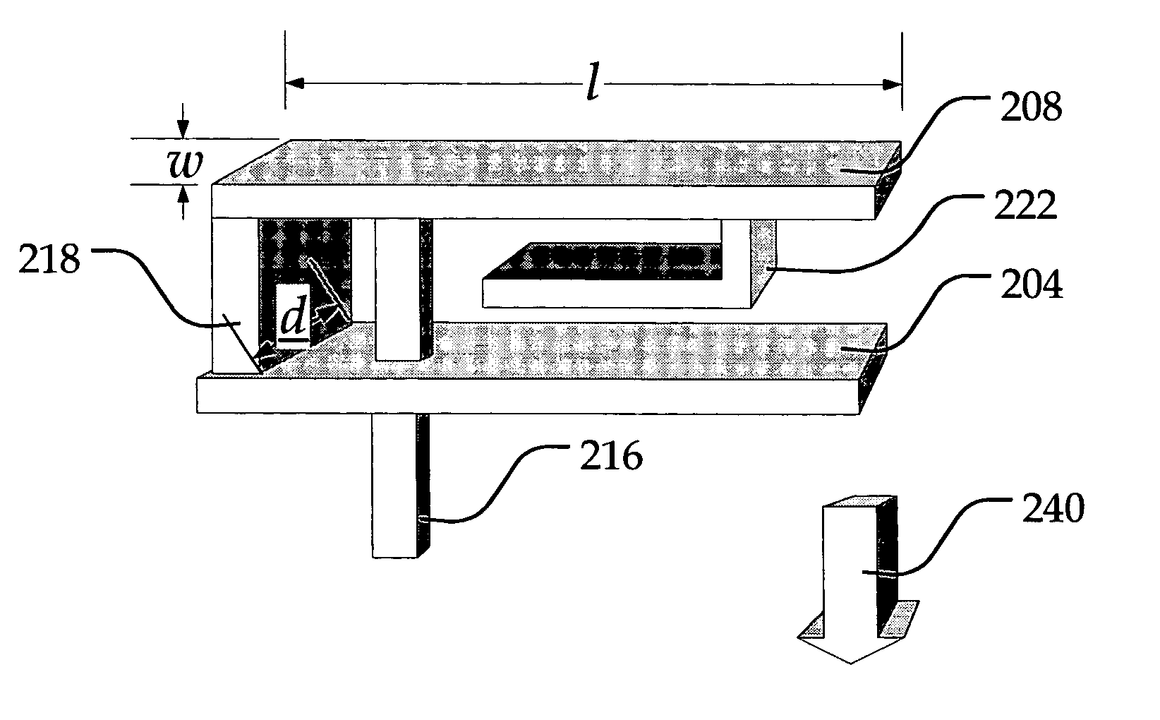
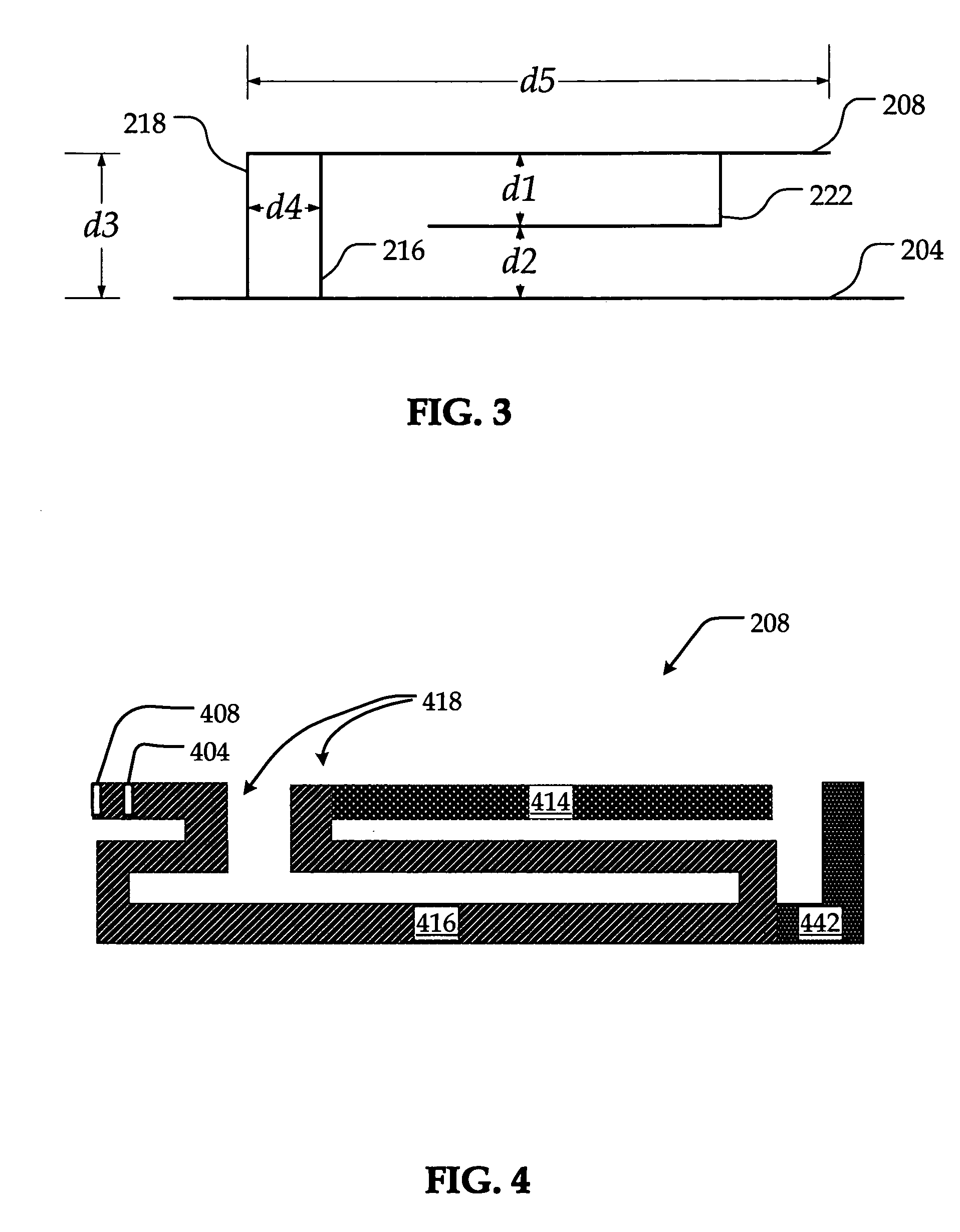
[0010] In summary, the present invention provides a novel and improved antenna configuration utilizing a capacitive element configured to provide high efficiency operation, and a tuning area that allows the antenna to be tuned independently of the capacitive element. As a result of this feature, the antenna can be tuned to the desired operating frequencies, while allowing the capacitive element to remain configured for optimal operating efficiency.
[0012] According to one embodiment of the antenna, the PIFA includes a capacitive loading section, providing for optimal antenna efficiency and thus optimal signal strength. Capacitive loading can be used to obtain a decrease in antenna size without suffering from any appreciable accompanying efficiency trade-off, and is optimized to allow the antenna to radiate efficiently.

Problems solved by technology

Although they enjoy widespread use, whip and helical antennas protrude from the package and are prone to breakage if the phone is mishandled.
Also, their length tends to interfere with the form factor of the device, especially for handheld or portable applications.
Despite these qualities, however, antenna designers continue to strive to improve operating efficiency, enhance multi-band operation, minimize losses resulting from capacitive tuning, and decrease the antenna's sensitivity to its surroundings.

Method used


Image

  • Planar inverted "F" antenna and method of tuning same
  • Planar inverted "F" antenna and method of tuning same
  • Planar inverted "F" antenna and method of tuning same

Examples


Embodiment Construction

[0025] The described example implemention is directed toward a highly efficient and tunable antenna. In this example, the antenna is in the form of a multi-band planar inverted F antenna (PIFA) having a capacitive element configured to provide high efficiency operation, and a tuning area that allows the antenna to be tuned while maintaining a desirable level of efficiency. More specifically, the tuning area can be configured to tune the antenna to the desired operating frequencies, while allowing the capacitive element to remain configured for optimal operating efficiency.

[0026] The antenna is described from time to time herein in terms of an example application, which includes dual-band CDMA and GSM radiotelephones operating at the 800 MHz and 1900 MHz frequency bands. After reading this description, it will become apparent to one of ordinary skill in the art how to implement the antenna for other applications in other wireless devices and operating at other frequency bands, inclu...


PUM


Abstract

A multiband planar inverted F antenna (PIFA) can provide improved performance and operating efficiency, and utilizes a capacitive element configured to provide high efficiency operation, and a tuning area that allows the antenna to be tuned independently of the capacitive element. As a result of this feature, the antenna can be tuned to the desired operating frequencies, while allowing the capacitive element to remain configured for optimal operating efficiency. The antenna can be configured in a loop for effective utilization of a given volume and can therefore be relatively small in size and high efficiency. A capacitive loading section can be included to allow improved antenna efficiency and radiation. Additionally, tuning section can be provided to allow the antenna to be tuned without adjusting the capacitive loading section. To obtain operation at an additional frequency band, a parasitic element or a slot configuration can be included.

Description

BACKGROUND [0001] 1. Field of the Invention [0002] The present invention relates generally to wireless communication devices, and more specifically to a relatively compact antenna (PIFA) suitable for use in such devices. [0003] 2. Description of Related Art [0004] Wireless communication equipment, such as cellular and other wireless telephones, wireless network (WiLAN) components, GPS receivers, mobile radios, pagers, and other wireless devices are enjoying increasing popularity in the contemporary marketplace. One reason for their increasing popularity is the large number of applications that such devices are now capable of supporting. Additional reasons include enhanced user interfaces, longer battery life, increasing affordability, and improved operability, among others. [0005] One critical feature of wireless devices not often contemplated by their users is the antenna, which provides a region of transition between a signal in a guided wave within the device and a free space wav...

Claims


Application Information

Patent Timeline
IPC IPC(8): H01Q1/38H01Q1/24
CPCH01Q1/38H01Q9/0442H01Q9/0421
Inventor OZKAR, METEPOILASNE, GREGORY
Owner KYOCERA WIRELESS
Learn More