
Printing unit and inking unit

a printing unit and inking technology, applied in printing, office printing, rotary letterpress machines, etc., can solve the problems of complex construction of inking units and printing units, and achieve the effect of simple and less expensive construction

Inactive Publication Date: 2006-02-23
MANROLANAD AG
View PDF29 Cites 4 Cited by
  • Summary
  • Abstract
  • Description
  • Claims
  • Application Information

AI Technical Summary

Benefits of technology

[0007] According to the present invention, a strict separation is maintained between inking unit rolls driven in oscillation and inking unit rolls driven in rotation within an inking unit. Therefore, the oscillating drive and rotary drive within an inking unit are accordingly separated or decoupled from each other. This has the advantage of a substantially simpler and therefore less expensive construction for an inking unit and a printing unit. The stroke during the oscillating movement may then be varied and set independently of the rotational speed of the rotary movement.

Problems solved by technology

Because, the inking unit rolls driven in oscillation are also driven in rotation, the inking units and printing units and the associated drives require complex construction.

Method used


Image

  • Printing unit and inking unit
  • Printing unit and inking unit
  • Printing unit and inking unit

Examples


Embodiment Construction

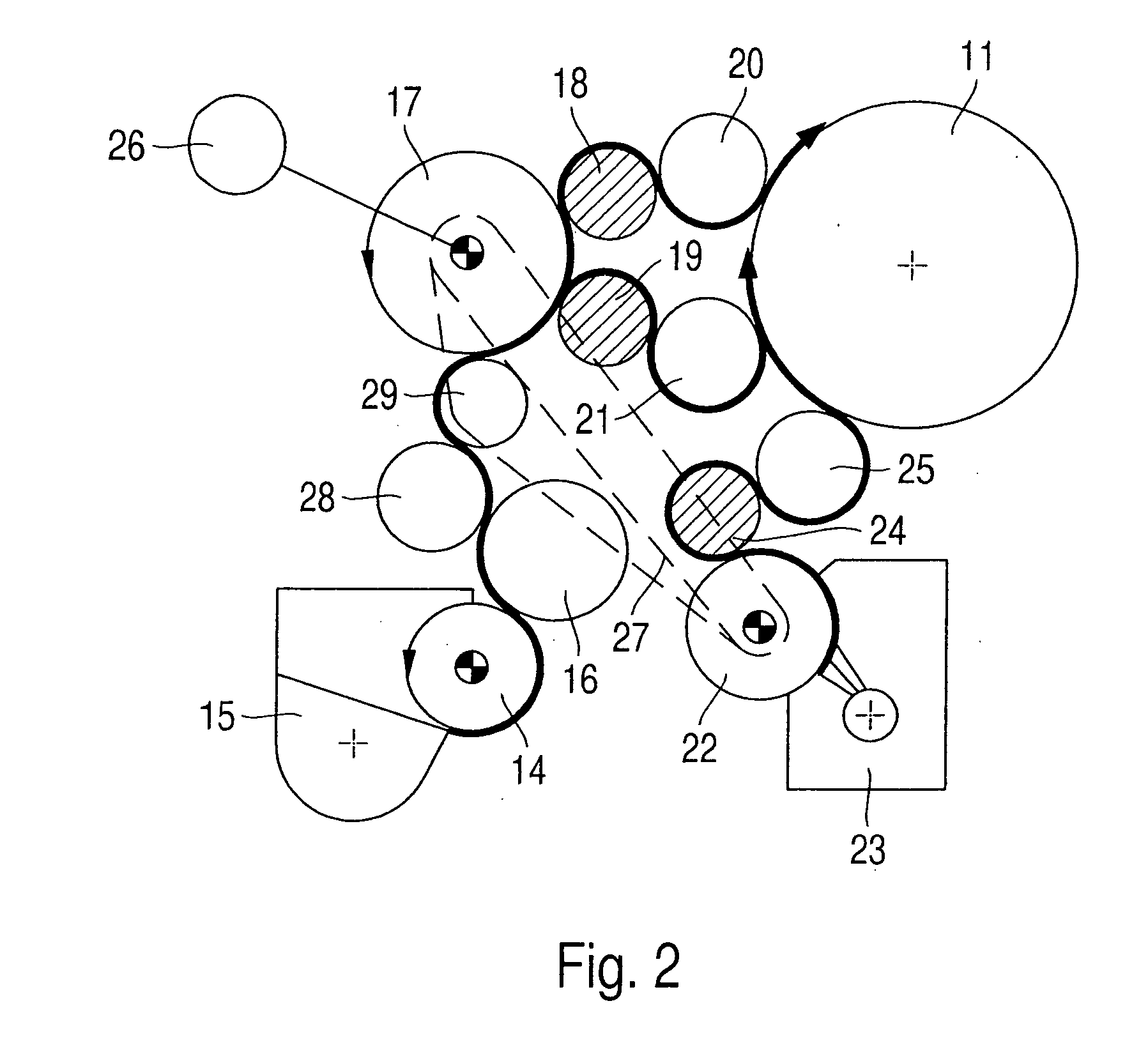
[0017] A press unit 10 of a printing unit according to the present invention is shown in FIG. 1. The press unit 10 includes a forme cylinder 11, a damping unit 12 and an inking unit 13. The inking unit 13 has a ductor roll 14, which removes printing ink from an ink fountain 15 and transfers it to a film roll 16 interacting with the ductor roll 14. Starting from the film roll 16, the printing ink is transferred to the forme cylinder 11 by a plurality of inking unit rolls 17, 18 and 19 connected downstream of the film roll 16 and also by ink applicator rolls 20 and 21 rolling on the forme cylinder 11. The damping unit 12 of the press unit 10 in FIG. 1 comprises a chromium-coated or ceramic-coated roll 22, to which damping solution kept ready in a damping solution supply 23 is applied. The chromium-coated or ceramic-coated roll 22 transfers the damping solution to the forme cylinder 11 by two rolls 24 and 25 arranged downstream of the chromium-coated or ceramic-coated roll 22. The roll...


PUM


Abstract

A printing unit includes a press unit having a forme cylinder, a transfer cylinder, an inking unit and, preferably, a damping unit. The inking unit of each press unit applies printing ink to a forme cylinder of the respective press unit in such a way that a ductor roll of an inking unit picks up printing ink kept ready in an ink fountain and applies it to the forme cylinder of the respective press unit by a film roll interacting with the ductor roll, inking unit rolls arranged downstream of the film roll, and at least one ink applicator roll rolling on the forme cylinder. Inking unit rolls driven in rotation and inking unit rolls driven in oscillation are are driven independently from one another on the drive side.

Description

BACKGROUND OF THE INVENTION [0001] The invention relates to a printing unit having at least one press unit with at least one forme cylinder, a transfer cylinder, an inking unit, and a damping unit, the inking unit of each press unit applying printing ink to a forme cylinder of the respective press unit in such a way that a ductor roll of an inking unit picks up printing ink from an ink fountain, the printing ink being applied to the forme cylinder of the respective press unit by a film roll interacting with the ductor roll, by inking unit rolls arranged downstream of the film roll and by at least one ink applicator roll rolling on the forme cylinder. Furthermore, the invention relates to an inking unit for a press unit of a press applying printing ink to a forme cylinder of the press unit such that a ductor roll of an inking unit picks up printing ink from an ink fountain, the printing ink being applied to the forme cylinder of the press unit by a film roll interacting with the duct...

Claims


Application Information

Patent Timeline
Patent Type & Authority Applications(United States)
IPC IPC(8): B41F31/14
CPCB41F31/15B41F31/02
Inventor KOPPELKAMM, GUNTER
Owner MANROLANAD AG
Learn More