
Compound bipolar ablation device and method

a bipolar ablation and compound technology, applied in the field of electrosurgical devices, can solve the problems of affecting the patient's recovery, so as to reduce the risk of injury, less insertion and removal, and less trauma to the patient

Inactive Publication Date: 2006-02-16
MEDTRONIC INC
View PDF99 Cites 20 Cited by
  • Summary
  • Abstract
  • Description
  • Claims
  • Application Information

AI Technical Summary

Benefits of technology

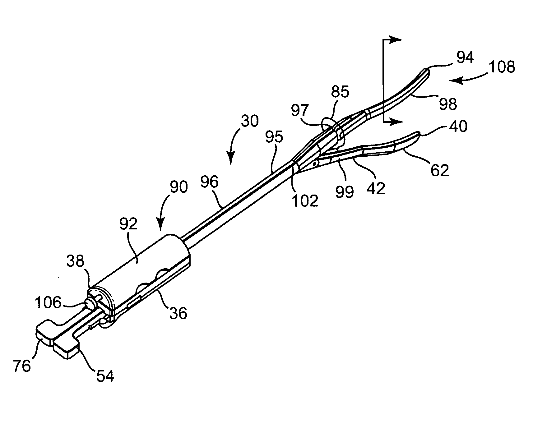
[0010] Accordingly, there is a need for a method and device that results in less trauma to the patient, fewer insertions and removals of the ablation tools, and more flexibility for selecting ablation configurations using a single tool to ablate target tissue of a patient's heart. A need also exists for a compound bipolar ablation device for minimally-invasive isolation of the pulmonary veins without completely occlude blood flow.
[0012] Embodiments of a method of the invention can include inserting a lower jaw assembly through an incision in the patient and inserting an upper jaw assembly through the incision. The method can include coupling the upper jaw assembly to the lower jaw assembly. The method can also include moving at least one of a proximal actuator and a distal actuator in order to position at least one of a proximal jaw and a distal jaw with respect to an upper jaw and providing ablation energy to at least one of an upper electrode, a proximal electrode, and a distal electrode.

Problems solved by technology

With sufficiently high levels of electrical energy between the two electrodes, heat is generated which is sufficient to denature proteins within the tissue and cause cell death.
High levels of voltage can actually cut and remove tissue (i.e., electrosurgery), while lower levels will simply create sufficient heat to cause cell damage, but leave the structure intact (i.e., catheter ablation) and block electrical pathways within the tissue.
Simply placing the Cardioblate-BP jaw onto an endoscopic handle has certain advantages, but there are significant limitations when trying to manipulate both jaws simultaneously through separate tissue spaces.

Method used


Image

  • Compound bipolar ablation device and method
  • Compound bipolar ablation device and method
  • Compound bipolar ablation device and method

Examples


Embodiment Construction

[0024] Before any embodiments of the invention are explained in detail, it is to be understood that the invention is not limited in its application to the details of construction and the arrangement of components set forth in the following description or illustrated in the following drawings. The invention is capable of other embodiments and of being practiced or of being carried out in various ways. Also, it is to be understood that the phraseology and terminology used herein is for the purpose of description and should not be regarded as limited. The use of “including,”“comprising” or “having” and variations thereof herein is meant to encompass the items listed thereafter and equivalents thereof as well as additional items. The terms “mounted,”“connected” and “coupled” are used broadly and encompass both direct and indirect mounting, connecting and coupling. Further, “connected” and “coupled” are not restricted to physical or mechanical connections or couplings, and can include el...


PUM


Abstract

Method and apparatus for ablating target tissue adjacent pulmonary veins of a patient. The ablation device can include a lower jaw assembly including a proximal jaw having a proximal electrode and a distal jaw having a distal electrode, and an upper jaw assembly including an upper jaw having an upper electrode. A proximal actuator can be movable between a first position in which the proximal jaw is open and a second position in which the proximal jaw is clamped with respect to the upper jaw. A distal actuator can be movable between a third position in which the distal jaw is open and a fourth position in which the distal jaw is clamped with respect to the upper jaw.

Description

RELATED APPLICATIONS [0001] This application claims the benefit of the filing date of U.S. Provisional Patent Application No. 60 / 576,245 filed on Jun. 2, 2004, which is incorporated herein by reference in its entirety.BACKGROUND [0002] Various types of electrocautery devices are used for ablating tissue. Typically, such devices include a conductive tip or blade which serves as one electrode in an electrical circuit which is completed via a grounding electrode coupled to the patient. With sufficiently high levels of electrical energy between the two electrodes, heat is generated which is sufficient to denature proteins within the tissue and cause cell death. [0003] By controlling the energy level, the amount of heat generated and the degree of tissue damage can also be controlled. High levels of voltage can actually cut and remove tissue (i.e., electrosurgery), while lower levels will simply create sufficient heat to cause cell damage, but leave the structure intact (i.e., catheter a...

Claims


Application Information

Patent Timeline
IPC IPC(8): A61B18/14
CPCA61B18/1442A61B2018/00577A61B2018/00375A61B2018/00363A61B2017/2938
Inventor ROTHSTEIN, PAUL T.BRISCOE, RODERICK E.FRANCISCHELLI, DAVID E.KIM, DAVID J. S.LUTTERMAN, ALISON
Owner MEDTRONIC INC
Learn More