Switching device for power distribution
a technology of switching device and power distribution, which is applied in emergency protective arrangements, substations, non-enclosed substations, etc., can solve problems such as reliability reduction, and achieve the effect of improving reliability
- Summary
- Abstract
- Description
- Claims
- Application Information
AI Technical Summary
Benefits of technology
Problems solved by technology
Method used
Image
Examples
embodiment 1
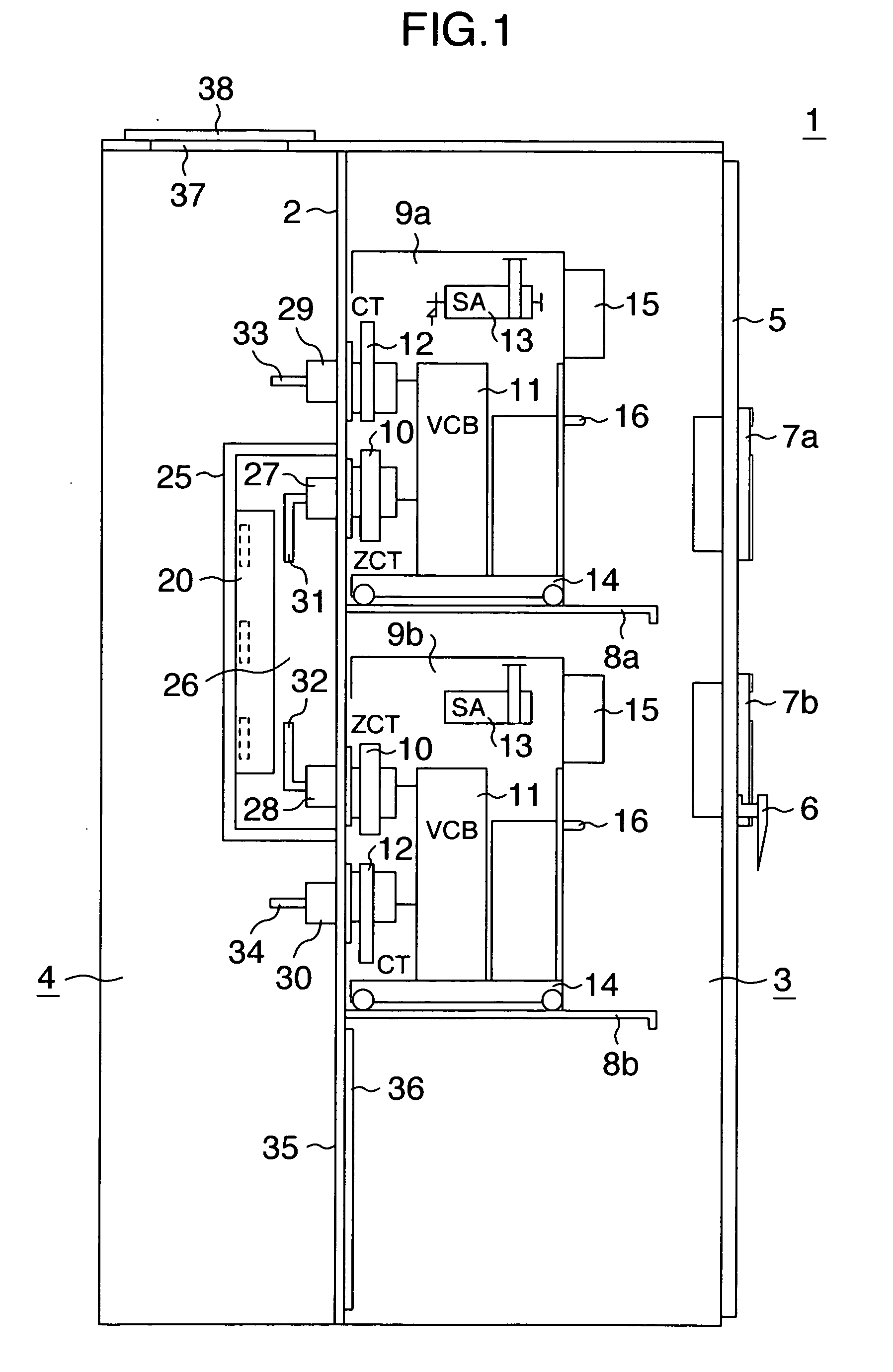
[0024]FIG. 1 shows one embodiment of the present invention. FIG. 1 is a side view showing the entire arrangement of an example in which two switching units for power distribution are stacked vertically one on another.
[0025] Referring to FIG. 1, a power receiving / distributing board 1 is partitioned by a partition plate 2 into a right section and a left section as shown in FIG. 1, wherein a front surface side of the right section defines a circuit breaker chamber 3, and a back surface side of the left section defines a cable chamber 4. A door 5 having a handle 6 is mounted on a front surface of the power receiving / distributing board 1. Two grounding (over-current) protection relays 7a and 7b are mounted to the door 5.
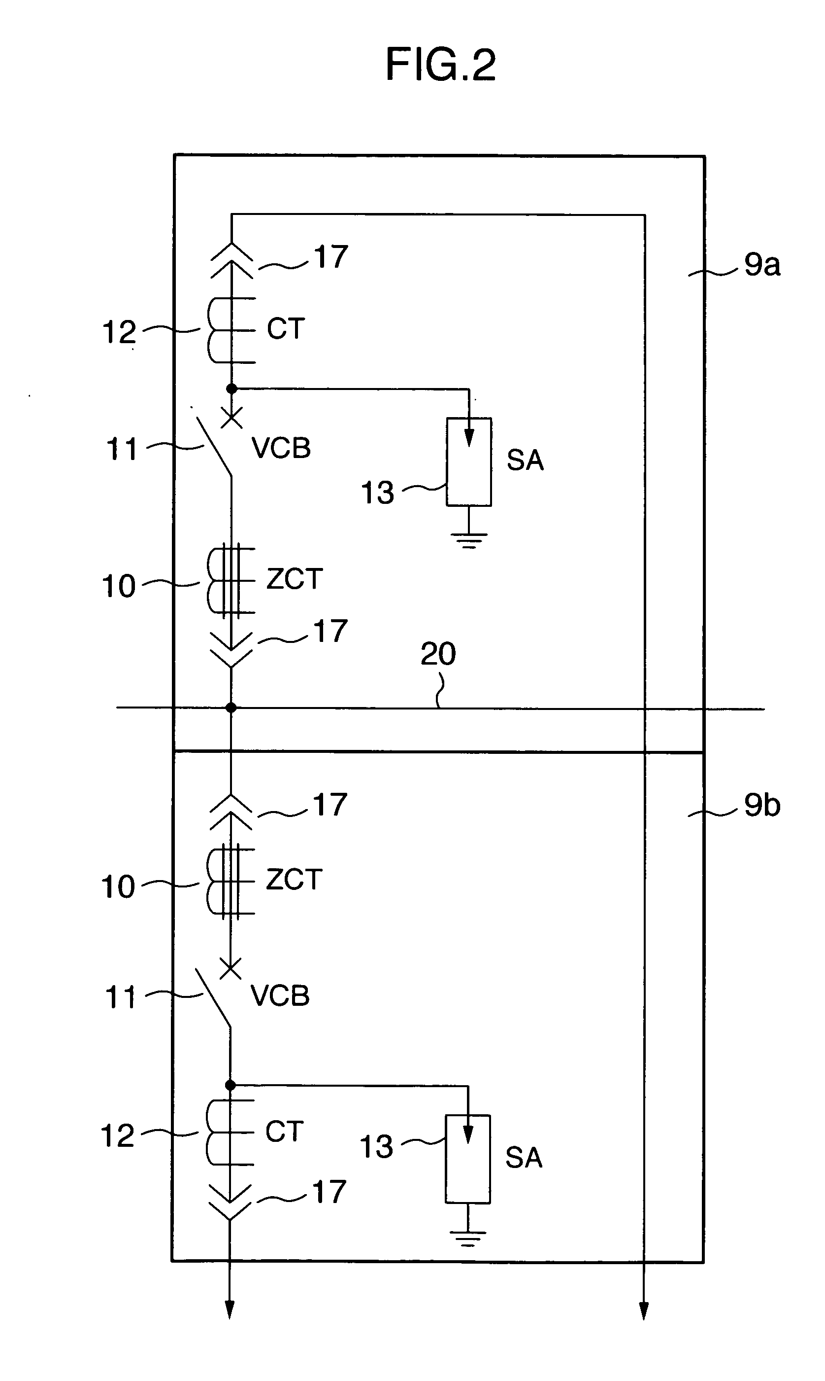
[0026] Two support plates 8a and 8b fixed to the partition plate 2 are disposed in the circuit breaker chamber 3. The two switching units 9a and 9b for power distribution are placed on the support plates 8a and 8b. The switching unit 9 for power distribution comprises a...
embodiment 2
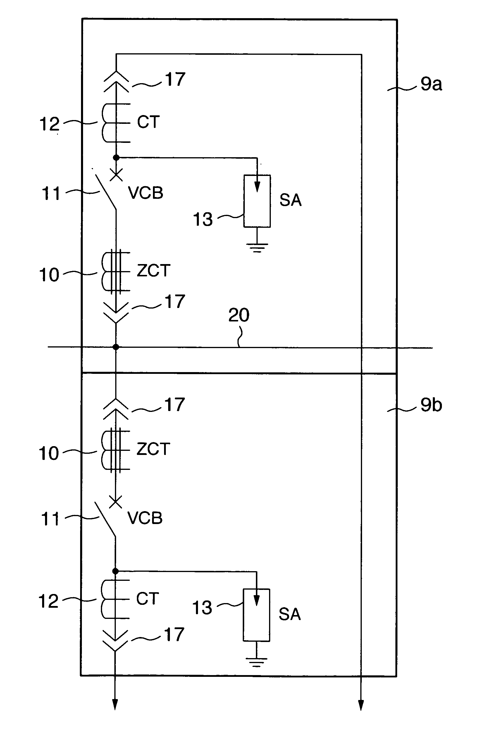
[0047] Another embodiment of the present invention is shown in FIG. 9. In the embodiment shown in FIG. 9, a zero-phase current transformer 10, a vacuum circuit breaker 11 and a current transformer 12 are shown, in a schematic connection view, as being disposed in a dispersed manner in a power receiving / distributing board 1 rather than being formed as a unit.
[0048] In FIG. 9, connecting fitments 17 are disposed at a power source side-portion and a load side-portion of the vacuum circuit breaker 11, so that only the circuit breaker 11 may be connected to and disconnected from a power source side-conductor 20 and a load side-conductor. Even if the zero-phase current transformer 10, the vacuum circuit breaker 11 and the current transformer 12 are disposed in the dispersed manner as described above, an advantageous effect similar to that in the embodiment 1 is obtained.
embodiment 3
[0049] A further embodiment of the present invention is shown in FIG. 10. In the embodiment shown in FIG. 10, a circuit breaker chamber 3 in a power receiving / distributing board 1 is formed so that it can be slid toward a front surface, thereby ensuring an inspecting space 50. The sliding of the circuit breaker chamber 3 can be achieved, for example, by a guide rail. To make access into the inspecting space 50, the circuit breaker chamber 3 is pulled out, thereby utilizing an inspecting aperture 51 formed in a ceiling plate and an inspecting aperture 35 provided in a lower portion of a partition plate 2.
[0050] In a case where a plurality of power receiving / distributing boards are disposed in a row arrangement, an inspecting space (an inspecting passage) 50 as shown in FIG. 11 is formed. The inspecting space 50 is formed over the entire row of the boards, but only one of the power receiving / distributing boards, which is required to be inspected, can be pulled out to form an inspecti...
PUM
 Abstract
Description
Claims
Application Information
 - Generate Ideas
- Intellectual Property
- Life Sciences
- Materials
- Tech Scout
- Unparalleled Data Quality
- Higher Quality Content
- 60% Fewer Hallucinations
Browse by: Latest US Patents, China's latest patents, Technical Efficacy Thesaurus, Application Domain, Technology Topic, Popular Technical Reports.
© 2025 PatSnap. All rights reserved.Legal|Privacy policy|Modern Slavery Act Transparency Statement|Sitemap|About US| Contact US: help@patsnap.com


