
Carbon heater

a heater and carbon technology, applied in the field of carbon heaters, can solve the problems of increasing complicated whole structure of the carbon heater, and achieve the effects of reducing the manufacturing cost of the carbon heater, and simplifying the connection structure between the carbon filament and the external electrodes

Active Publication Date: 2006-02-16
LG ELECTRONICS INC
View PDF20 Cites 15 Cited by
  • Summary
  • Abstract
  • Description
  • Claims
  • Application Information

AI Technical Summary

Benefits of technology

The present invention provides a carbon heater with support parts that are integrally formed at a carbon filament while being protruded from the carbon filament in the direction perpendicular to the longitudinal direction of the carbon filament such that the support parts are supported inside a tube. This simplifies the connection structure between the carbon filament and external electrodes, making it easy to connect them with reduced manufacturing costs. The carbon heater has a simplified connection structure and is easy to manufacture.

Problems solved by technology

As a result, the carbon filament connection structure is complicated, and therefore, the whole structure of the carbon heater is complicated.
Consequently, the manufacturing costs of the carbon heater are considerably increased.

Method used


Image

  • Carbon heater
  • Carbon heater
  • Carbon heater

Examples


Embodiment Construction

[0037] Now, preferred embodiments of the present invention will be described in detail with reference to the accompanying drawings.

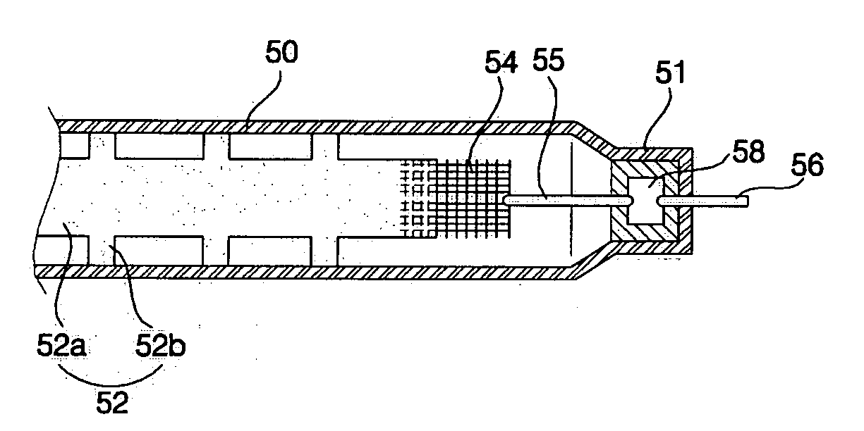
[0038]FIGS. 4 and 5 show a carbon heater according to a preferred embodiment of the present invention. FIG. 4 is a front view, in section, illustrating principal components of the carbon heater according to the preferred embodiment of the present invention, and FIG. 5 is a plan view, in section, illustrating principal components of the carbon heater according to the preferred embodiment of the present invention.

[0039] s shown in FIGS. 4 and 5, the carbon heater according to the preferred embodiment of the present invention comprises: a quartz tube 50 having tube sealing parts 51 formed at both ends thereof; a carbon filament 52 disposed longitudinally in the quartz tube 50 for serving as a heating element, the carbon filament 52 being formed in the shape of a sheet; external electrodes 56 disposed at the tube sealing parts 51 of the quartz tube 50, res...


PUM

PropertyMeasurementUnit
temperatureaaaaaaaaaa
shapeaaaaaaaaaa
thermal efficiencyaaaaaaaaaa

Abstract

Disclosed herein is a carbon heater. The carbon heater comprises a carbon filament disposed in a tube for serving as a heating element. The carbon filament has support parts integrally formed at the carbon filament while being protruded from the carbon filament in the direction perpendicular to the longitudinal direction of the carbon filament such that the support parts are supported inside the tube. Consequently, the carbon filament is more stably supported in the tube by the support parts, whereby the service life of the carbon heater is increased, and easy and convenient design and assembly of the carbon heater is accomplished.

Description

BACKGROUND OF THE INVENTION [0001] 1. Field of the Invention [0002] The present invention relates to a carbon heater incorporating a carbon fiber or a carbon filament, which is used as a heating element, and, more particularly, to a carbon heater having support parts, which are integrally formed at the carbon filament while being protruded from the carbon filament such that the support parts are supported inside a quartz tube. [0003] 2. Description of the Related Art [0004] Generally, a carbon heater is a heater that uses a filament made of carbon as a heating element. As it became known that the carbon heater has excellent thermal efficiency, does not harm the environment when the carbon is discarded, and provides several effects, such as far infrared radiation, deodorization, sterilization, and antibacterial activity, the carbon heater has been increasingly used in room-heating apparatuses and drying apparatuses as well as heating apparatuses. [0005]FIG. 1 is a perspective view sc...

Claims


Application Information

Patent Timeline
Patent Type & Authority Applications(United States)
IPC IPC(8): H05B3/10
CPCH05B3/009H05B3/44H05B3/145H05B3/04H05B3/14
Inventor KIM, WAN SOOKIM, YANG KYEONGLEE, YOUNG JUN
Owner LG ELECTRONICS INC
Learn More