Display rack with slidable channel trays
a technology of display racks and channel trays, which is applied in the field of display racks, can solve the problems of difficult to refill the articles, and is, of course, a very time-consuming operation
- Summary
- Abstract
- Description
- Claims
- Application Information
AI Technical Summary
Benefits of technology
Problems solved by technology
Method used
Image

Examples
embodiment 1
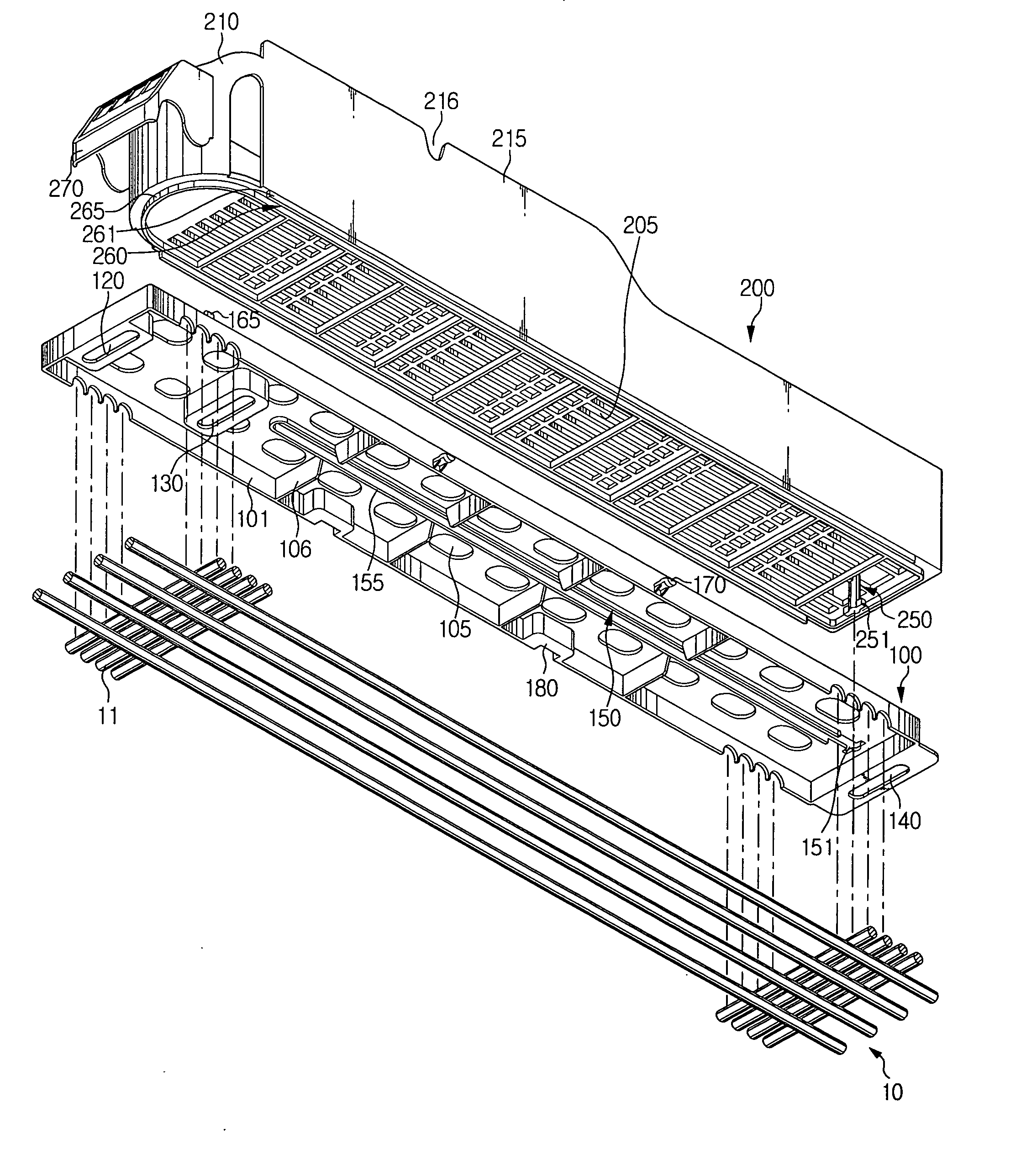
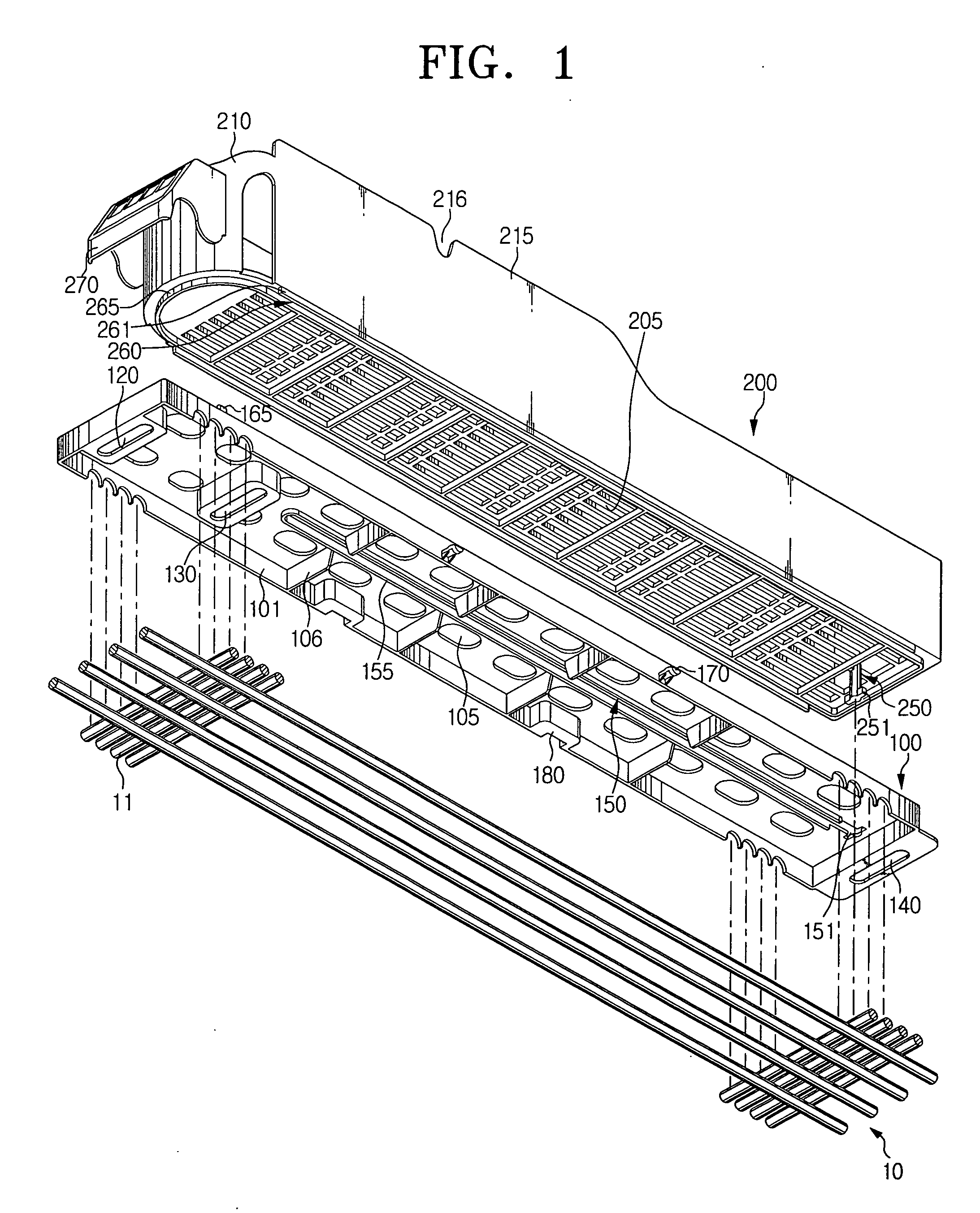
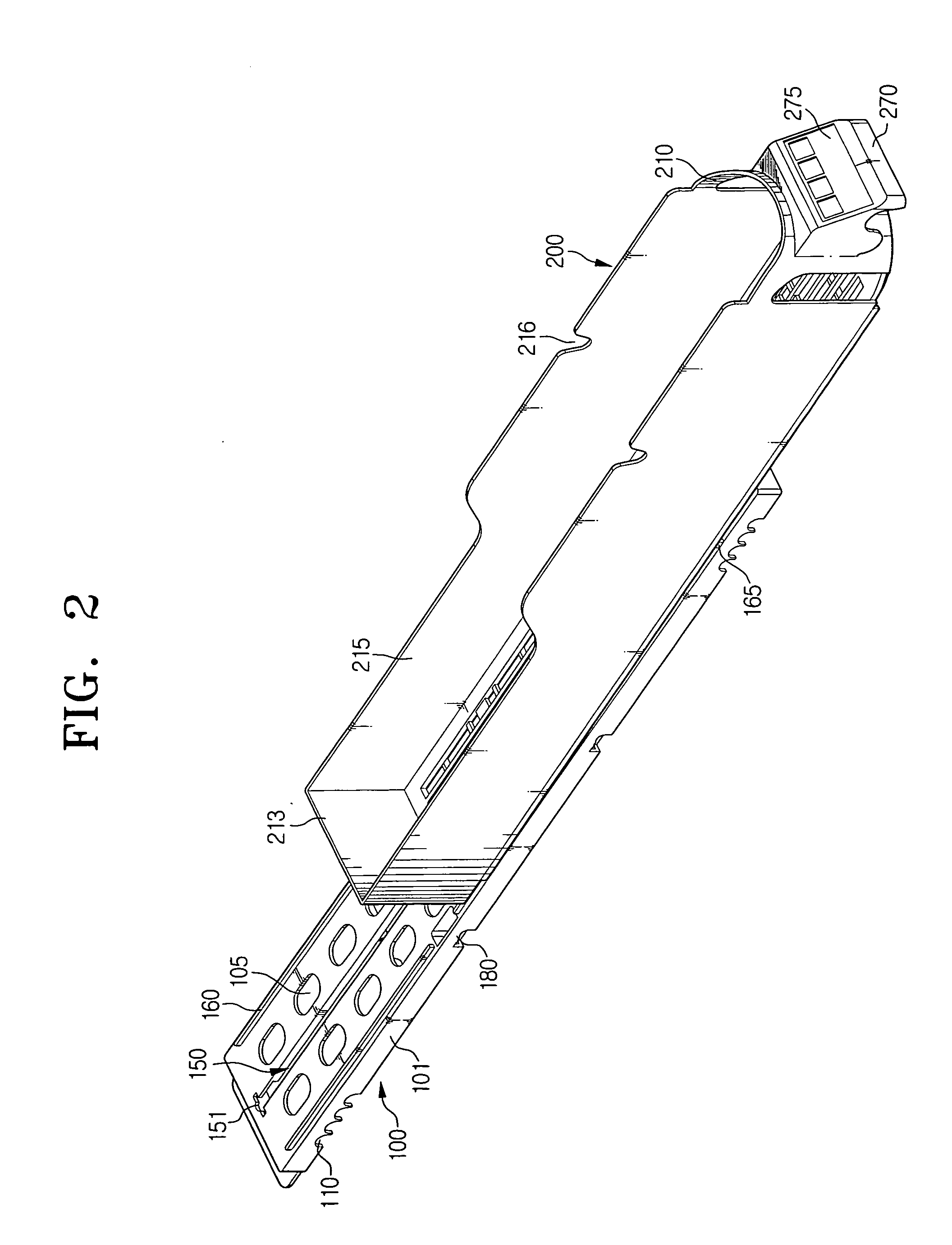
[0027]FIG. 1 shows a display rack module according to the present invention comprising a channel tray 200 and a channel base 100 together with a fragmentary wire shelf 10 of a display case and FIG. 2 shows a channel tray 200 mounted on a channel base 100 with the channel tray 200 partly slid out from a channel base 100.
[0028] As shown, the display rack module according to the present invention comprises a channel base 100 and a channel tray 200. The channel base 100 may be secured by conventional fasteners such as bolts and nuts or by using other conventional fixing method on the wire shelf 10 which is firmly installed in the display case (not shown). The channel tray 200 is mounted slidably along the channel base 100 so that the channel tray 200 can be slid forwardly from the channel base 100 and / or can be returned onto the channel base 100 without being disassembled from the channel base 100.
[0029] For illustrating a method for fixing the channel base 100 on the wire shelf 10, i...
embodiment 2
[0043] Embodiment 1 is applicable to a display rack for articles not too heavy to be stocked in a channel tray 200. However, when articles to be stocked in a channel are too heavy, the channel base 100 may be deformed or broken owing to the elongate guide slot 150 or the enlarged portion 251 of the protrusion 250 may be broken by substantial moment of the channel tray 200 with articles on refilling mode especially in case of a long channel.
[0044] Accordingly, a display rack module for displaying many heavy articles needs more rigid structure and sliding mechanism. Embodiment 2 and 3, as shown FIGS. 4 to 11, provide more rigid types of a display rack module.
[0045] Embodiment 2 improves slidable mating structure between the channel base 100 and the channel tray 200 of the Embodiment 1 only. Therefore, descriptions are omitted for vent holes 305, bolt holes 320 and330, keys 370 and key-holes 380 of the channel base 300; and vent holes 405, a front wall 410, a rear wall 413, side wall...
embodiment 3
[0052] Embodiment 3 is similar to the construction of Embodiment 2, however, the slidable mating structure between the guide grooves 460 of the channel tray 400 and the guide rails 360 of the channel base 300, the front wall 410 and the knob 470, and the connecting structure between the channel bases 300 are modified from those of the Embodiment 2.
[0053] Therefore, explanation of elements which are identical or similar to those in Embodiment 2 is omitted.
[0054] FIGS. 8 to 11 show a display rack module according to the Embodiment 3 of the present invention.
[0055] As shown in FIGS. 8 to 10, a channel tray 600 has a pair of guide grooves 660 extended downwardly from both longitudinal side end portions of bottom surface of the channel tray 660. And a channel base 500 has a pair of guide rails 560 extended upwardly from both longitudinal side end portions of upper surface of the channel base 500. A guide groove 660 of a channel tray 600 has a longitudinal grooves 668 opened toward the...
PUM
 Abstract
Description
Claims
Application Information
 - R&D
- Intellectual Property
- Life Sciences
- Materials
- Tech Scout
- Unparalleled Data Quality
- Higher Quality Content
- 60% Fewer Hallucinations
Browse by: Latest US Patents, China's latest patents, Technical Efficacy Thesaurus, Application Domain, Technology Topic, Popular Technical Reports.
© 2025 PatSnap. All rights reserved.Legal|Privacy policy|Modern Slavery Act Transparency Statement|Sitemap|About US| Contact US: help@patsnap.com