
Lane keeping assist device for vehicle

a technology for keeping assist devices and vehicles, which is applied in anti-collision systems, non-deflectable wheel steering, underwater vessels, etc., can solve the problems of increasing the manufacturing cost of the device, the inability to accurately obtain the curvature in the direction the vehicle is traveling in, and the increase of the manufacturing cos

Inactive Publication Date: 2006-02-09
AISIN SEIKI KK
View PDF8 Cites 119 Cited by
  • Summary
  • Abstract
  • Description
  • Claims
  • Application Information

AI Technical Summary

Benefits of technology

[0012] In light of the foregoing, the present invention provides a lane keeping assist device for a vehicle, which includes a steering control means operated in accordance with an operation of a steering wheel by an operator for controlling a steering state in accordance with traveling state of a vehicle on a road, a detection means for lane of travel for detecting a lane mark indicating the lane of travel based on continuous images of the road captured by an image capturing means, a navigation system for detecting information of a road configuration including positional coordinates by a predetermined distance in the direction the vehicle traveling in, a state detection means for detecting a steering state and traveling state of the vehicle, a vehicle state amount calculation means for calculating a state amount of the vehicle in accordance with the steering state and the traveling state of the vehicle and detected result of the detection means for lane of travel, a first road curvature calculation means for calculating a first road curvature in the direction the vehicles traveling in on the basis of detection result of the state detection means and calculation result of the vehicle state amount calculation means, a second road curvature calculation means for calculating a second road curvature in the direction the vehicle traveling in on the basis of positional coordinates by a predetermined distance in the direction the vehicle traveling in detected by the navigation system, a road curvature estimation means for estimating road curvature in the direction the vehicle traveling in on the basis of calculation result of the first road curvature calculation means and calculation result of the second road curvature calculation means, and a target state amount setting means for setting a target state amount relative to the vehicle on the basis of the traveling state and the steering state of the vehicle detected by the state detection means and road curvature estimated by the road curvature estimation mean

Problems solved by technology

However, because those known forward camera and rearward camera are only capable for securing images in the vicinity of the vehicle and because the distant images assumes blurred, curvature in the direction the vehicle is traveling in can not be obtained accurately relative to curved lane marks.
Thus, the curvature had to be obtained from a traveling locus in the past to be applied, and because a camera which has already been boarded on the vehicle is not converted to detect lane marks and another forward camera with high performance is applied, manufacturing cost of the device is increased.
However, provided that the positional coordinates of the traveling direction of the vehicle is specified using only the detected information from the navigation system, a navigation system with high precision is required because the detection of the positional coordinates is heavily depending on the precision of the navigation system, which increases the manufacturing cost.
In addition, in case the forward camera with high precision is required, the manufacturing cost assumes extremely high.

Method used


Image

  • Lane keeping assist device for vehicle
  • Lane keeping assist device for vehicle
  • Lane keeping assist device for vehicle

Examples


first embodiment

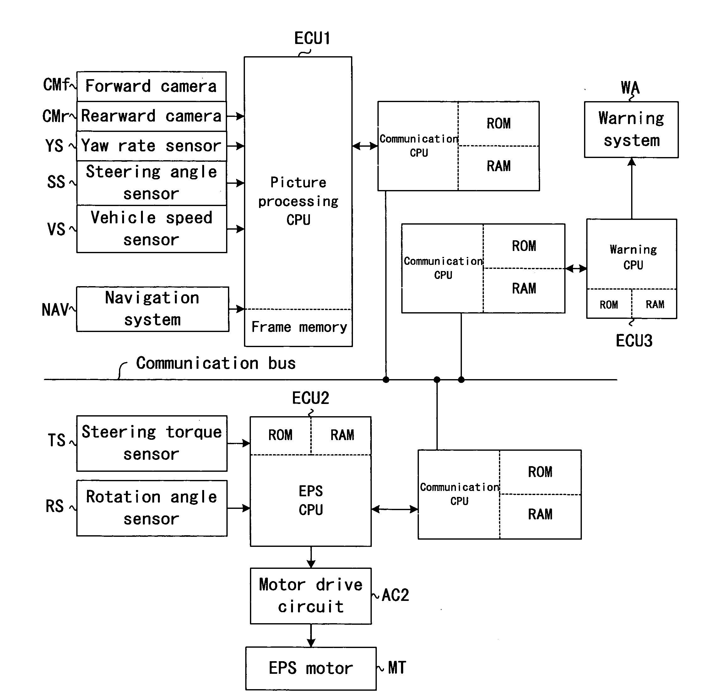
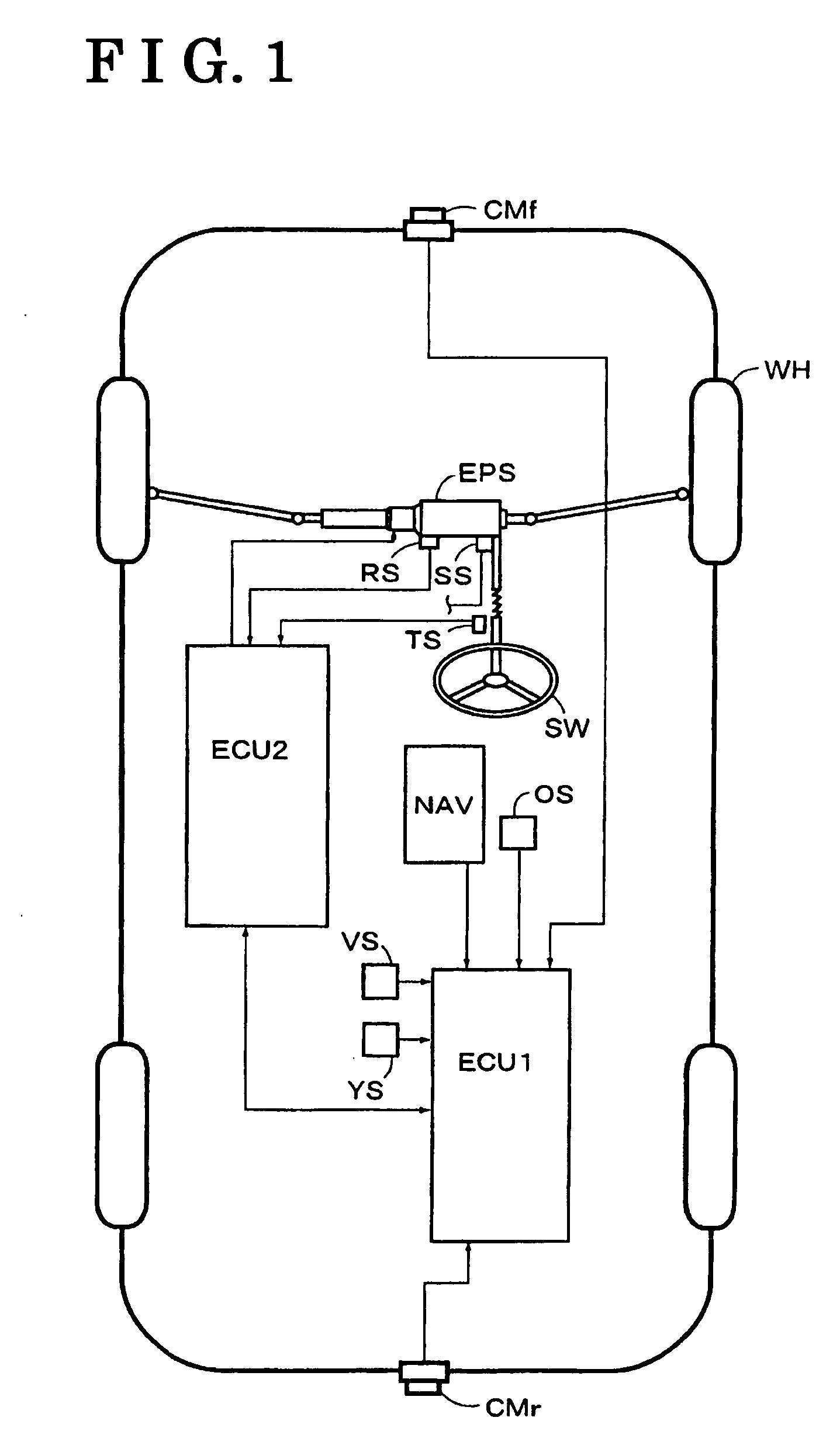
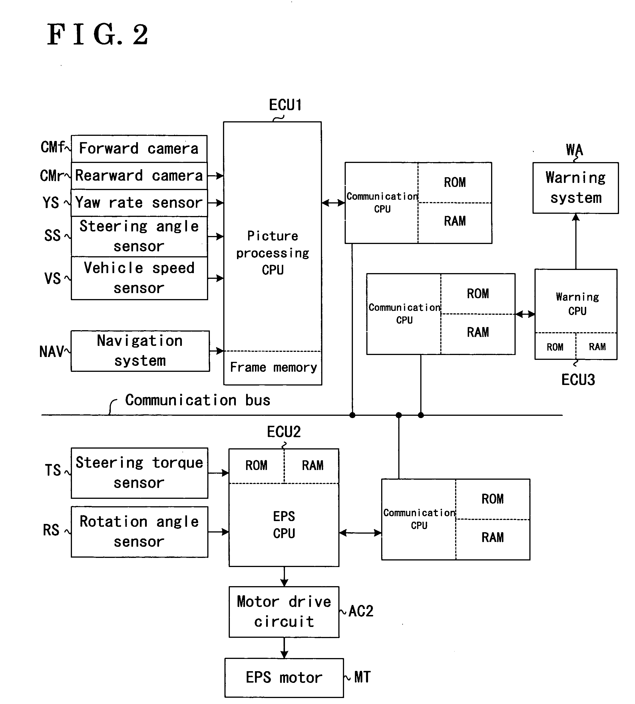
[0030] As shown in FIG. 1, a lane keeping assist device according to the present invention includes a camera CMf provided at a front end of a vehicle for observing forward including a CCD camera serving as an image capturing means (i.e., top in FIG. 1) and a camera CMr provided at a rear end of the vehicle for observing backward of the vehicle, which also includes a CCD camera serving as the image capturing means. Providing one of the cameras CMf, CMr is sufficient to capture images. The lane keeping assist device includes an electric power steering system EPS serving as a steering control means. A known electric power steering system is applied as the electric power steering system EPS for detecting steering torque affecting a steering shaft by an operation of a steering wheel SW by a driver by means of a steering torque sensor TS, controlling an EPS motor MT (shown in FIG. 2) in accordance with the detected steering torque, steering front wheels (WH shown in FIG. 1 represents all ...

second embodiment

[0061] the present invention will be explained with reference to FIG. 14. Using positional coordinates at a predetermined position in the direction of a vehicle VH (shown in FIG. 14) traveling in among the information of the road configuration detected by the navigation system NAY, the positional coordinates may be inputted into the electronic control unit ECU 1. More particularly, as shown in FIG. 14, a road curvature (ρ) in the vicinity of the position of the own vehicle is estimated by the method of least squares from several points among the plural road coordinates (i.e., positional coordinates shown with dots in FIG. 14) detected by the navigations system NAV, and x-y coordinates having an axis in parallel with tangents shown with two dotted line in FIG. 14 as x-axis is set. X coordinate value (xlt) of target coordinate point (a cross shown in FIG. 14) in the direction of the vehicle VH traveling in is set on the basis of the vehicle speed Vx of the vehicle VH, and y coordinate...


PUM


Abstract

A lane keeping assist device for a vehicle includes a steering control device, a detection device for lane of travel for assisting travel of the vehicle in a lane of travel in accordance with detection results and steering state and traveling state of the vehicle. Road curvature in a direction the vehicle traveling in is estimated on the basis of a first road curvature calculated on the basis of calculation result of a vehicle state amount calculation device and detection result of a state detection device, and a second road curvature calculated on the basis of positional coordinates by a predetermined distance in the direction the vehicle traveling in detected by a navigation system NAV. Target state amount is set on the basis of the road curvature and the steering state and traveling state of the vehicle.

Description

CROSS REFERENCE TO RELATED APPLICATIONS [0001] This application is based on and claims priority under 35 U.S.C. §119 with respect to Japanese Patent Applications No. 2004-212044 filed on Jul. 20, 2004 and No. 2004-212045 filed on Jul. 20, 2004, the entire content of which are incorporated herein by reference. FIELD OF THE INVENTION [0002] The present invention relates to a lane keeping assist device for a vehicle. More particularly, the present invention pertains to a lane keeping assist device which includes a steering control means operated in accordance with an operation of a steering wheel by a driver for controlling a steering state in accordance with a state of road surface of travel of a vehicle and a detection means for lane of travel for detecting a lane of travel on the basis of continuous images of a road surface captured by means of an image capturing means in order to assist the vehicle to travel keeping in a lane. BACKGROUND [0003] Known lane keeping assist devices for...

Claims


Application Information

Patent Timeline
IPC IPC(8): G06F17/00B62D6/00
CPCB62D15/025B62D6/00
Inventor AKITA, TOKIHIKO
Owner AISIN SEIKI KK
Learn More