
Object storage devices, systems, and related methods

a technology for object storage and positioning, applied in the direction of supporting devices, instruments, electrical devices, etc., can solve the problems of high complexity of storage and management of libraries in these types of objects, low locating tolerance or tolerance, damaged hotels, multi-well containers, etc., to minimize the risk of system components being damaged, accurately positioned or located, and accurate positioning

Inactive Publication Date: 2006-02-09
IRM
View PDF8 Cites 85 Cited by
  • Summary
  • Abstract
  • Description
  • Claims
  • Application Information

AI Technical Summary

Benefits of technology

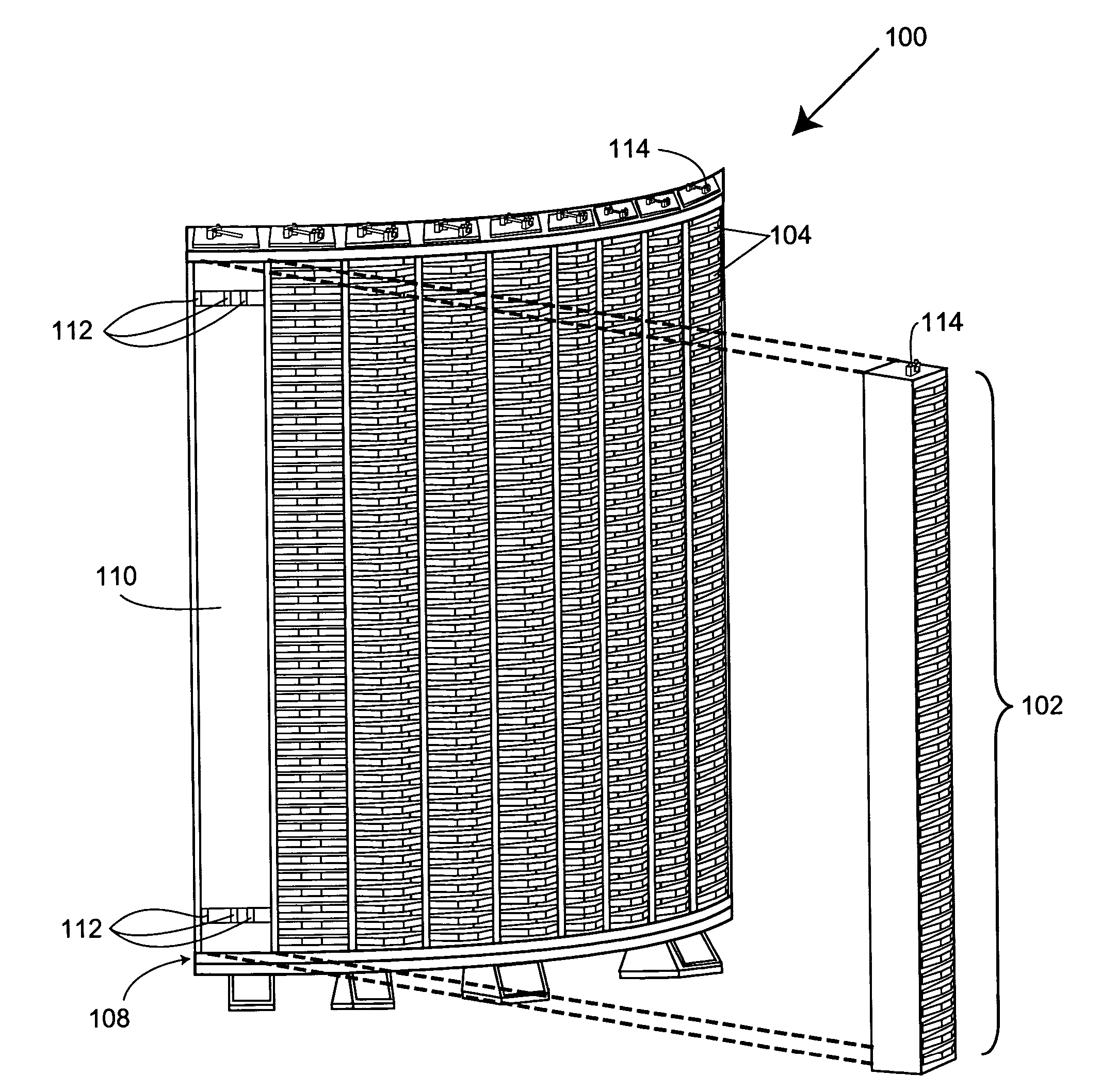
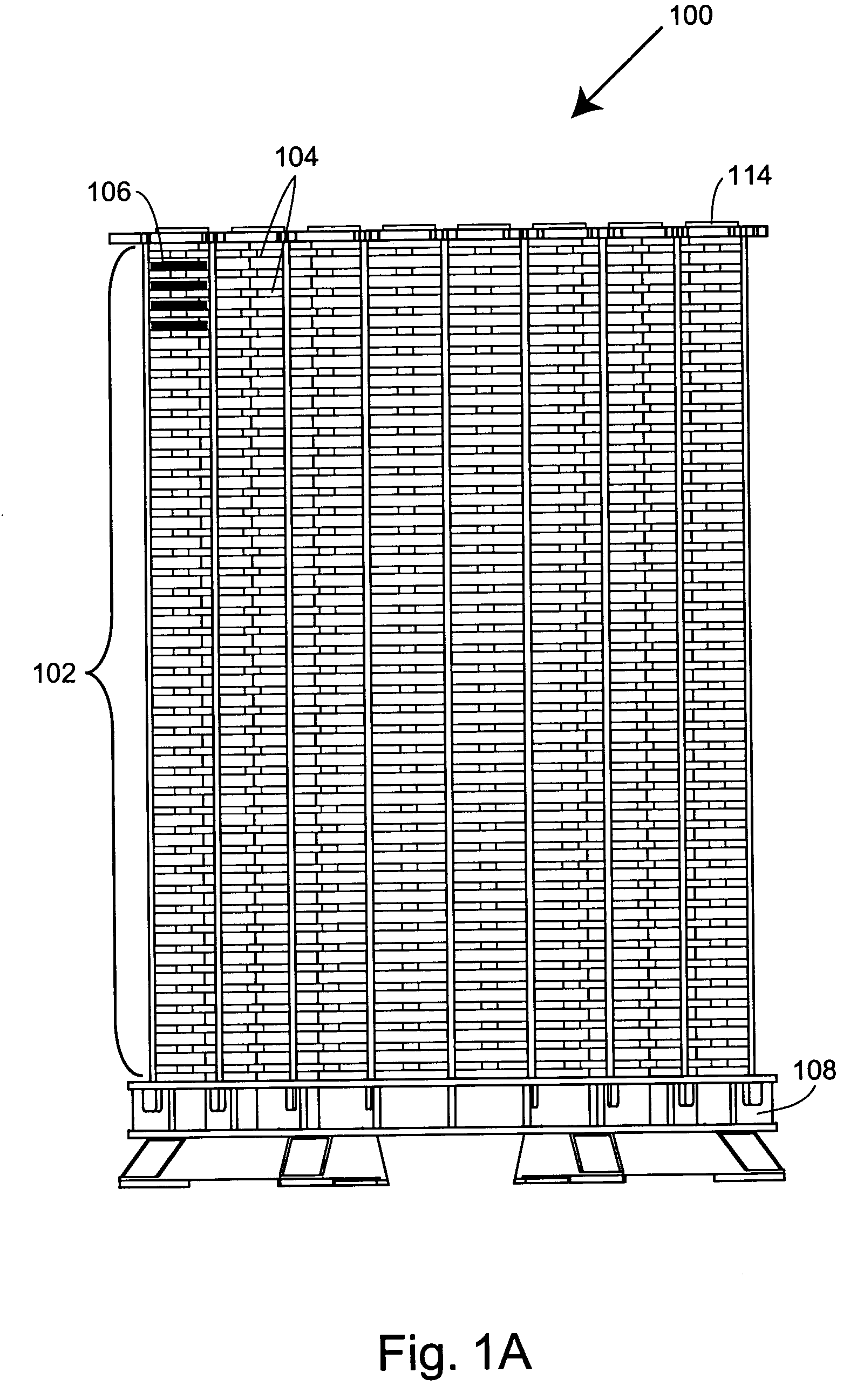
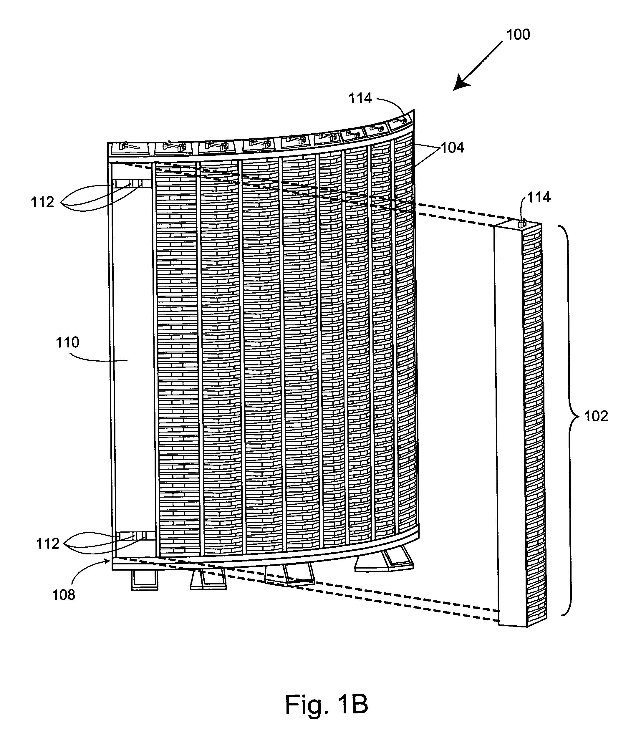
[0006] The present invention provides object storage devices that include object storage modules that can be rapidly, accurately, and reliably positioned or located relative to support elements of the devices. Objects are typically supported on shelves of the object storage modules. In systems that include the object storage devices of the invention, the accurately positioned object storage modules minimize the risk of system components being damaged, e.g., when robotic gripping mechanisms grasp objects, such as multi-well containers, substrates, or the like supported on the shelves of the object storage modules. The invention also provides methods of positioning or locating these object storage modules relative to, e.g., substantially fixed support elements.
[0007] In one aspect, the invention provides a modular object storage device that includes at least one object storage module including at least one shelf that is structured to support at least one object. For example, the shelf is optionally structured to support at least one container (e.g., a multi-well plate, a multi-well reaction block, etc.) and / or at least one substrate (e.g., a silicon wafer, a solid support comprising arrayed molecules, or the like). Typically, the object storage module includes a housing having multiple, vertically stacked shelves, e.g., in the form of a hotel. The modular object storage device also includes a support element comprising at least one object storage module receiving area that is structured to receive the object storage module. The object storage module receiving area includes at least one set of at least three elevated alignment surfaces that together substantially correspond to at least a portion of a contour of the object storage module. The contour of the object storage module optionally includes a shape selected from, e.g., a regular n-sided polygon, an irregular n-sided polygon, a triangle, a square, a rectangle, a trapezoid, a circle, an oval, a portion thereof, or the like. In addition, the modular object storage device also includes at least one position adjustment component that is attached or attachable to the object storage module and the support element. The position adjustment component is structured to move the object storage module into contact with each of the elevated alignment surfaces, thereby positioning or locating the object storage module in a desired position (e.g., accurately aligned relative to an automated object translocation component, etc.). In certain embodiments, the modular object storage device includes multiple object storage modules, e.g., for increased storage capacity.

Problems solved by technology

The storage and management of libraries in these types of objects can be highly complex.
The positioning of multi-well container hotels relative to these robotic translocation devices generally has a very low locating tolerance or tolerance for misalignment, as errors in the relative positioning of these devices may lead to damaged hotels, multi-well containers, and / or robotic devices when they unintentionally contact one another during operation.
Many pre-existing approaches to positioning or aligning object storage modules, such as multi-well container storage modules, lack adequate positioning accuracy, and / or efficiency.

Method used


Image

  • Object storage devices, systems, and related methods
  • Object storage devices, systems, and related methods
  • Object storage devices, systems, and related methods

Examples


Embodiment Construction

I. Definitions

[0043] Before describing the present invention in detail, it is to be understood that this invention is not limited to particular embodiments. It is also to be understood that the terminology used herein is for the purpose of describing particular embodiments only, and is not intended to be limiting. Units, prefixes, and symbols are denoted in the forms suggested by the International System of Units (SI), unless specified otherwise. Numeric ranges are inclusive of the numbers defining the range. Further, unless defined otherwise, all technical and scientific terms used herein have the same meaning as commonly understood by one of ordinary skill in the art to which the invention pertains. The terms defined below, and grammatical variants thereof, are more fully defined by reference to the specification in its entirety.

[0044] The term “aligned” refers to a positioning or state of adjustment of two or more items in relation to each other. In certain embodiments, for exam...


PUM


Abstract

The present invention provides modular object storage devices that include object storage modules and support elements that include object storage module receiving areas that are structured to receive the object storage modules. The modular object storage devices also include position adjustment components that are structured to move the object storage modules into contact with elevated alignment surfaces of the object storage module receiving areas to align the object storage module in desired positions. The invention also provides systems and related methods of positioning object storage modules.

Description

CROSS-REFERENCES TO RELATED APPLICATIONS [0001] This application claims the benefit of U.S. Provisional Application No. 60 / 598,929, filed Aug. 4, 2004, the disclosure of which is incorporated by reference in its entirety for all purposes.FIELD OF THE INVENTION [0002] The present invention relates generally to the storage of objects and to the positioning of object storage devices. In certain embodiments, for example, the invention provides modular object storage devices having support elements relative to which removable object storage modules are accurately and precisely positioned. BACKGROUND OF THE INVENTION [0003] The storage of objects in an organized manner that facilitates ready access to the objects is significant in a wide variety of contexts. To take one example, many modern scientific endeavors involve large numbers of processes performed in parallel to enhance throughput among other reasons. These processes include, inter alia, combinatorial chemical syntheses, protein c...

Claims


Application Information

Patent Timeline
Patent Type & Authority Applications(United States)
IPC IPC(8): H05K7/00
CPCB01L9/52B01L9/523B01L2200/025G01N2035/0425B01L2300/0829G01N35/028B01L2300/0819
Inventor SHAW, CHRISTOPHER M.DOWNS, ROBERT CHARLES
Owner IRM
Learn More