
Compact fluorescent lamps

a fluorescent lamp, compact technology, applied in the direction of gas discharge lamp details, electric discharge tubes, electrical apparatus, etc., can solve problems such as inherent siz

Inactive Publication Date: 2006-01-26
SHANGHAI ZHENGBEI LIGHTING APPLIANCE
View PDF1 Cites 7 Cited by
  • Summary
  • Abstract
  • Description
  • Claims
  • Application Information

AI Technical Summary

Benefits of technology

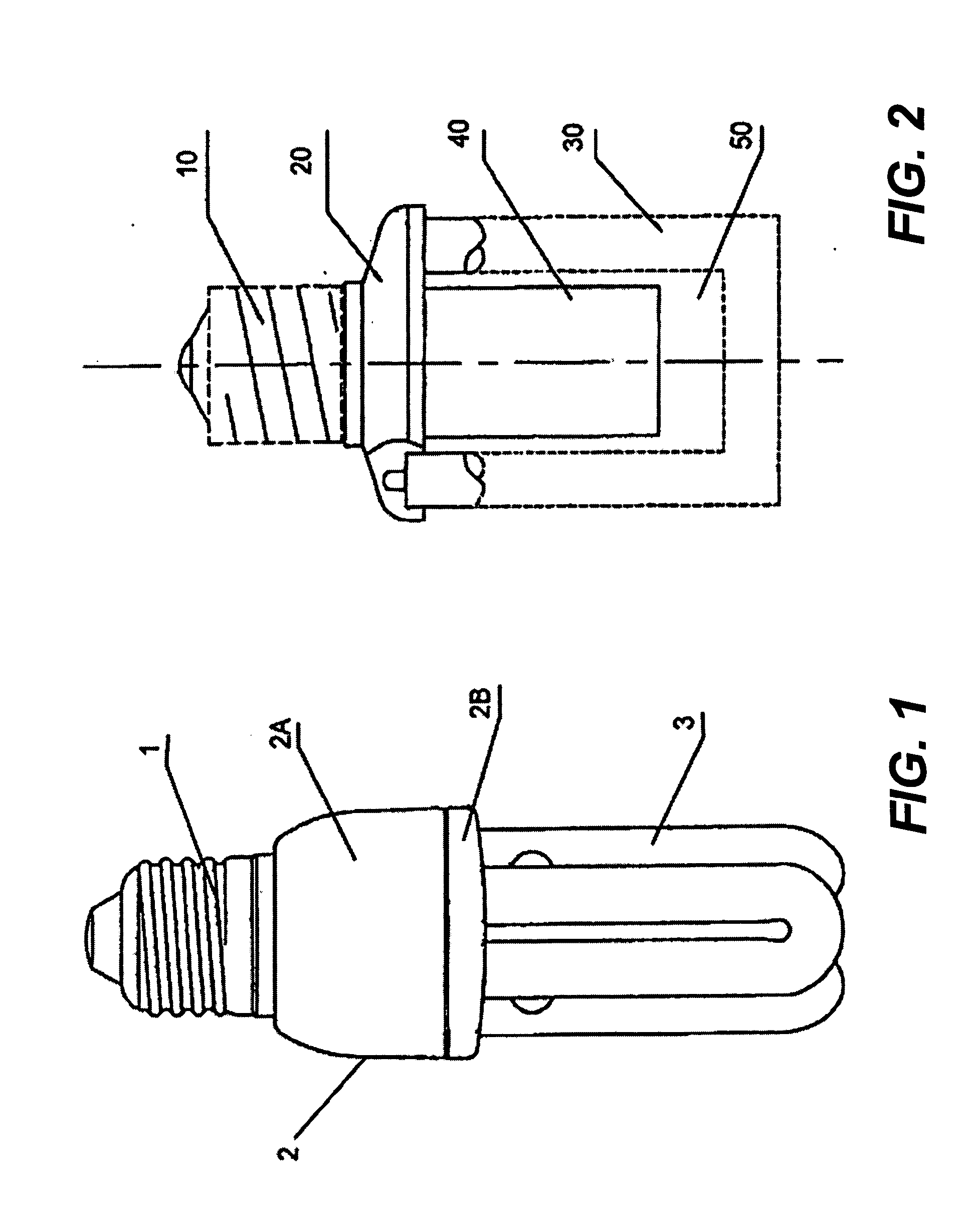
[0006] One of the issues in the structure of the traditional fluorescent lamp is the inherent size because the base(1), housing (2) and tubes(3) are connected directly in a line with the embedded ballast in the housing (2). Based on the current manufacturing technology, an electronic ballast is quite large in size. Therefore the size of the housing (2) is subject to that of the ballast. As a result, the housing (2) contributes significantly to the overall size or length of the lamp. Essentially the housing in the traditional fluorescent lamp restricts the compactness of a fluorescent lamp, especially in those lower power or shorter tube lamps, and becoming a barrier for further miniaturization and compactness of low power and energy saving fluorescent lamps. There is thus a need for energy saving fluorescent lamps in compact size.
[0006] One of the issues in the structure of the traditional fluorescent lamp is the inherent size because the base(1), housing (2) and tubes(3) are connected directly in a line with the embedded ballast in the housing (2). Based on the current manufacturing technology, an electronic ballast is quite large in size. Therefore the size of the housing (2) is subject to that of the ballast. As a result, the housing (2) contributes significantly to the overall size or length of the lamp. Essentially the housing in the traditional fluorescent lamp restricts the compactness of a fluorescent lamp, especially in those lower power or shorter tube lamps, and becoming a barrier for further miniaturization and compactness of low power and energy saving fluorescent lamps. There is thus a need for energy saving fluorescent lamps in compact size.

Problems solved by technology

One of the issues in the structure of the traditional fluorescent lamp is the inherent size because the base(1), housing (2) and tubes(3) are connected directly in a line with the embedded ballast in the housing (2).
Essentially the housing in the traditional fluorescent lamp restricts the compactness of a fluorescent lamp, especially in those lower power or shorter tube lamps, and becoming a barrier for further miniaturization and compactness of low power and energy saving fluorescent lamps.

Method used


Image

  • Compact fluorescent lamps
  • Compact fluorescent lamps

Examples


Embodiment Construction

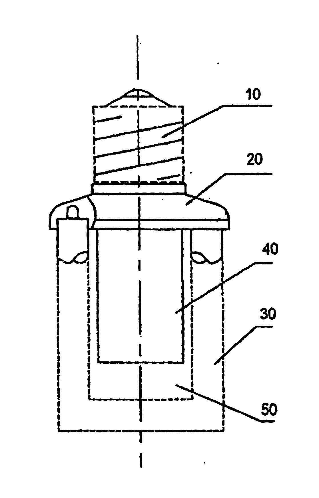
[0010] The present invention pertains to techniques of designing compact fluorescent lamps and a method for doing the same. According to one aspect of the present invention, instead of embedding a ballast in a chamber between a lamp base and lamp tubes, the ballast is enclosed in a space formed by the lamp tubes. As a result, the overall size of a fluorescent lamp is reduced. Fluorescent lamps manufactured in accordance with the present invention appear more compact. In one embodiment, the fluorescent lamps appear closer to the traditional incandescent lamps.

[0011] Reference herein to “one embodiment” or “an embodiment” means that a particular feature, structure, or characteristic described in connection with the embodiment can be included in at least one embodiment of the invention. The appearances of the phrase “in one embodiment” in various places in the specification are not necessarily all referring to the same embodiment, nor are separate or alternative embodiments mutually e...


PUM


Abstract

Techniques of designing compact fluorescent lamps are disclosed. Instead of embedding a ballast in a chamber between a lamp base and lamp tubes, the ballast is substantially enclosed in a space formed by the lamp tubes. As a result, the overall size of a fluorescent lamp is reduced.

Description

BACKGROUND OF THE INVENTION [0001] 1. Field of the Invention [0002] The present invention relates to the area of fluorescent lamps. Particularly, the present invention is related to a compact fluorescent lamp enclosing a ballast in a manner that the overall size of the lamp is significantly reduced and the method for making the same. [0003] 2. Description of the Related Art [0004] Fluorescent-based energy saving lamps have been used widely in residential and industrial lightings because of their high efficiency in light outputs and energy. Moreover, these types of lamps are being highly promoted by the government. [0005]FIG. 1 shows a structure for a traditional fluorescent lamp. As shown in the figure, the lamp includes a lamp base (1), a housing (2) and a lamp tubes (3). The housing (2) includes a housing cover (2A) and a housing space (2B), wherein the housing cover (2A) and a housing space (2B) form a chamber to embed a ballast therein. The tubes (3) are constructed on top of th...

Claims


Application Information

Patent Timeline
Patent Type & Authority Applications(United States)
IPC IPC(8): H01J5/48H01J5/50H01J61/32H01J61/56
CPCH01J61/327
Inventor CAI, ZHONGWEIYANG, JINZHONG
Owner SHANGHAI ZHENGBEI LIGHTING APPLIANCE
Learn More