
Double layered intraluminal graft

a double-layered, intraluminal technology, applied in the field of intraluminal devices, can solve the problems of affecting the size of the artery in which the catheter is inserted, the inability to insertion, and the inability to withstand the insertion, so as to avoid unnecessary bulking

Inactive Publication Date: 2006-01-19
WL GORE & ASSOC INC
View PDF22 Cites 7 Cited by
  • Summary
  • Abstract
  • Description
  • Claims
  • Application Information

AI Technical Summary

Benefits of technology

[0020] In still a further embodiment, the first and second tubular graft bodies are longitudinally reinforced along their length by a longitudinally reinforcing malleable wire. The longitudinally reinforcing wire may be positioned between two circumferentially reinforcing wires. Several longitudinally reinforcing wires may be positioned along the length of both the first and the second tubular graft bodies. Each wire may be generally straight in shape or may have a zig-zag or sinusoidal shape. The presence of a longitudinally reinforcing wire has the advantage of reinforcing the tubular graft bodies such that neither tubular graft body is forced into a compressed state along its longitudinal axis.
[0052] In a further embodiment, the first tubular graft body may include only one leg member, the first tubular graft body having an aperture rather than a second leg member. In this case, the second tubular member is adapted such that it has one leg member that may be inserted through the aperture of the first tubular graft body. In place of the second leg member, the second tubular member has an aperture through which the leg member of the first tubular graft body may be inserted. This embodiment has the advantage that each tubular graft member is symmetrical in shape. Typically, with trouser grafts, the tubular graft body must be positioned in a certain orientation, such that one leg member extends into one vessel and the other leg member extends into another vessel. In the case of a graft for bridging an aneurysm spanning the bifurcation of the aorta into the iliac arteries, one of the leg members will extend towards or into the left iliac artery and the other leg member will extend towards or into the right iliac artery. Radio-opaque markers positioned on the graft are typically used to ensure the correct positioning of the graft. In the present embodiment, however, because the first tubular graft body is symmetrical in shape there is no need to use such markers to ensure correct positioning of the tubular graft body and the one leg member will extend towards or into the desired iliac artery. A second tubular graft member may then be inserted, the second tubular graft member having one leg member that extends towards or into the other iliac artery.

Problems solved by technology

There may be a number of problems associated with such known intraluminal devices which may include rupture of the intraluminal graft due to general wear or damage upon insertion into the vessel.
The limitation in this regard is the size of the artery in which the catheter is being inserted.
If the catheter is too large in diameter, it is not suitable for insertion into the femoral artery of a patient.
Further, in so-called “trouser grafts”, the graft may have a tendency to “kink” in an area of the graft immediately above the area of bifurcation.

Method used


Image

  • Double layered intraluminal graft
  • Double layered intraluminal graft
  • Double layered intraluminal graft

Examples


Embodiment Construction

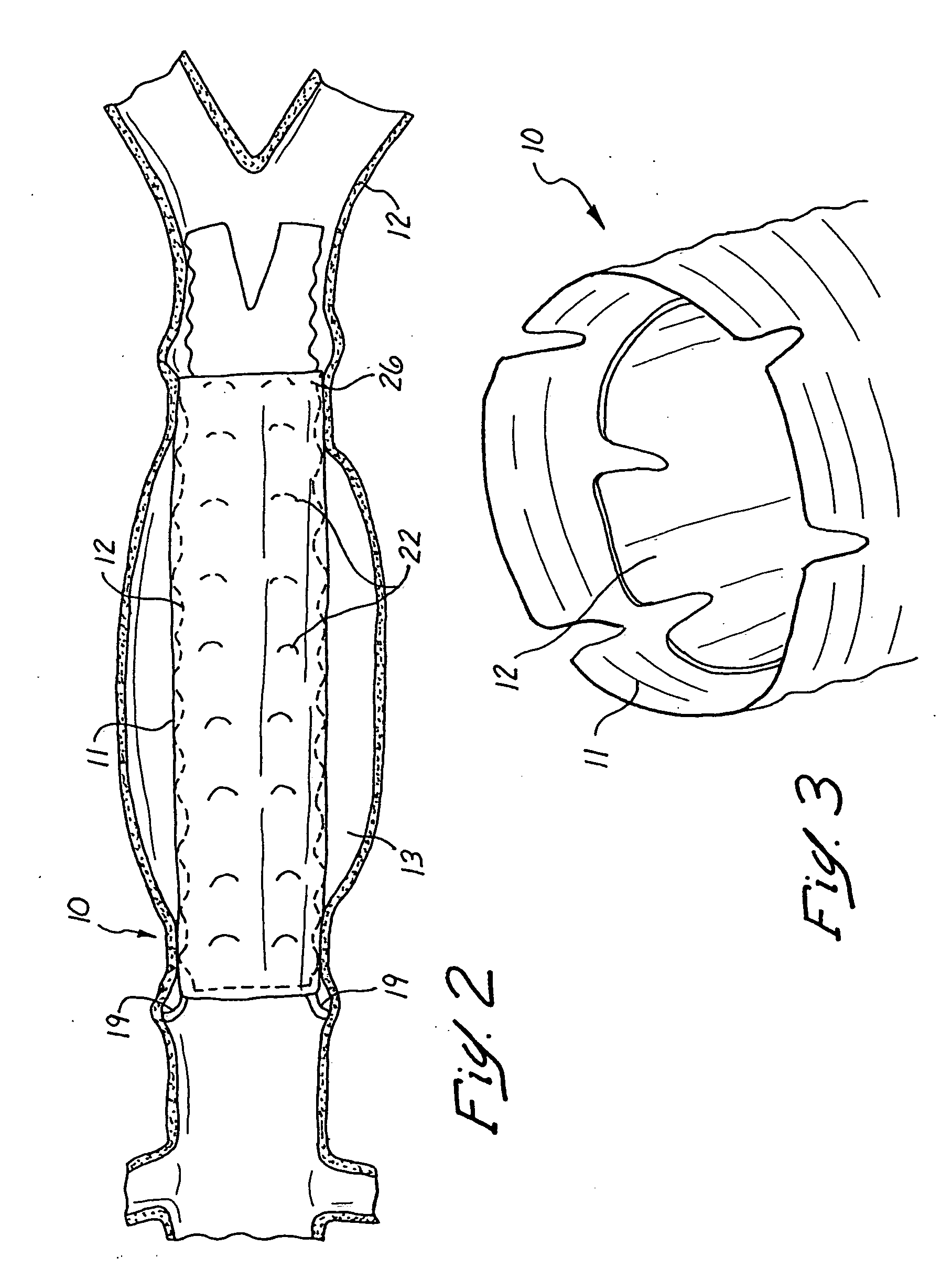
[0072] An intraluminal device according to the present invention is generally shown as 10 in the drawings. The intraluminal device 10 comprises two separate components, a first graft 11 and a second graft 12.

[0073] The device 10 is adapted for insertion transfemorally into a patient to achieve bridging and occlusion of an aneurysm 13 present in the aorta 14. As shown in FIG. 1, the aorta 14 bifurcates to form the common iliac arteries 15 which in turn divide into the internal 16 and external 17 iliac arteries. The external iliac artery in turn forms the femoral artery 18. The first graft 11 is inserted inside a catheter (not shown) and introduced into one of the femoral arteries 18 in a leg of a patient. Once the catheter is located appropriately with its proximal end in the aorta 14, the first graft 11 is ejected from the catheter and expanded using a balloon so that the first graft 11 is in intimate contact along its length and around its full periphery with the surrounding vesse...


PUM


Abstract

Supplemental intraluminal graft extension achieved by cuff-means substantially fortify and enhance endovascularly emplaced systems, particularly for bridging aneurysms. Multiple embodiments based upon overlapping of at least two segments are taught. Cuff-means likewise have applications to restore patency to, or substantially enhance, prior failing emplacements of both home-made and other commercial devices.

Description

[0001] The present invention depends from Australian Provisional Patent Application No. PQ 3027, filed 23 Sep. 1999 in the Commonwealth of Australia, full Paris Convention priority is hereby earnestly solicited and reserved. FIELD OF THE INVENTION [0002] The present invention relates to an intraluminal device for use in the treatment of aneurysmal or stenotic disease. BACKGROUND OF THE INVENTION [0003] It is known to use intraluminal grafts and stents of various designs for the treatment of aneurysms such as aortic aneurysms and occlusive diseases affecting the vasculature or other vessels comprising, inter alia, the hepatobiliary and genito-urinary tracts (which are all hereinafter “vessels”). It is known to form such an intraluminal device of a sleeve in which is disposed a plurality of self-expanding wire stents (see Balko A. et al (1986) Transfemoral Placement of Intraluminal Polyurethane Prosthesis for Abdominal Aortic Aneurysms, 40 Journal of Surgical Research 40, 305-309; Mir...

Claims


Application Information

Patent Timeline
Patent Type & Authority Applications(United States)
IPC IPC(8): A61F2/06A61F2/07A61F2/89
CPCA61F2/07A61F2/89A61F2002/075A61F2002/065
Inventor WHITE, GEOFFREYYU, WEIYUN
Owner WL GORE & ASSOC INC
Learn More