
Biofunctional dental implant

a dental implant and biofunctional technology, applied in the field of biofunctional dental implants, can solve the problems of common conventional crown screws, screw loosening and screw breakage, and sometimes broken screws

Active Publication Date: 2006-01-19
SAPIAN SCHUBERT L
View PDF13 Cites 122 Cited by
  • Summary
  • Abstract
  • Description
  • Claims
  • Application Information

AI Technical Summary

Benefits of technology

[0008] A biofunctional dental implant is disclosed by which a crown portion is affixed to a root portion that is implanted below a dental patient's gum line within an implant socket that is formed in the patient's bone structure. The root portion may have one or more screw threads extending therearound, anti-rotational notches formed therein, and sharp edged barbs projecting therefrom by which to engage the patient's bone structure so as to anchor the root portion in place and prevent the root portion from rotating relative to the implant socket within which the root portion is located. A screw

Problems solved by technology

However, problems such as crown breakage, screw loosening and screw breakage are inherent problems with the conventional crown implant.
More particularly, screws commonly associated with conventional crowns sometimes break because of over tightening and due to tension and lateral stress to which the crown is subjected during use.
As dental professionals will understand, it is difficult and time consuming to retrieve and / or repair such broken screws.
Once the root portion of the implant is installed, it may take several months to achieve suitable bone integration of the root portion with the surrounding bone structure thereby resulting in increased loading time before the crown can be reliably attached.
What is more, many crowns cannot easily absorb and distribute shock and other physical forces that are generated during chewing.
Such crowns may be susceptible to damage or reduced life and may be unable to provide the function of a natural tooth and the quality of mastication associated therewith.

Method used


Image

  • Biofunctional dental implant
  • Biofunctional dental implant
  • Biofunctional dental implant

Examples


Embodiment Construction

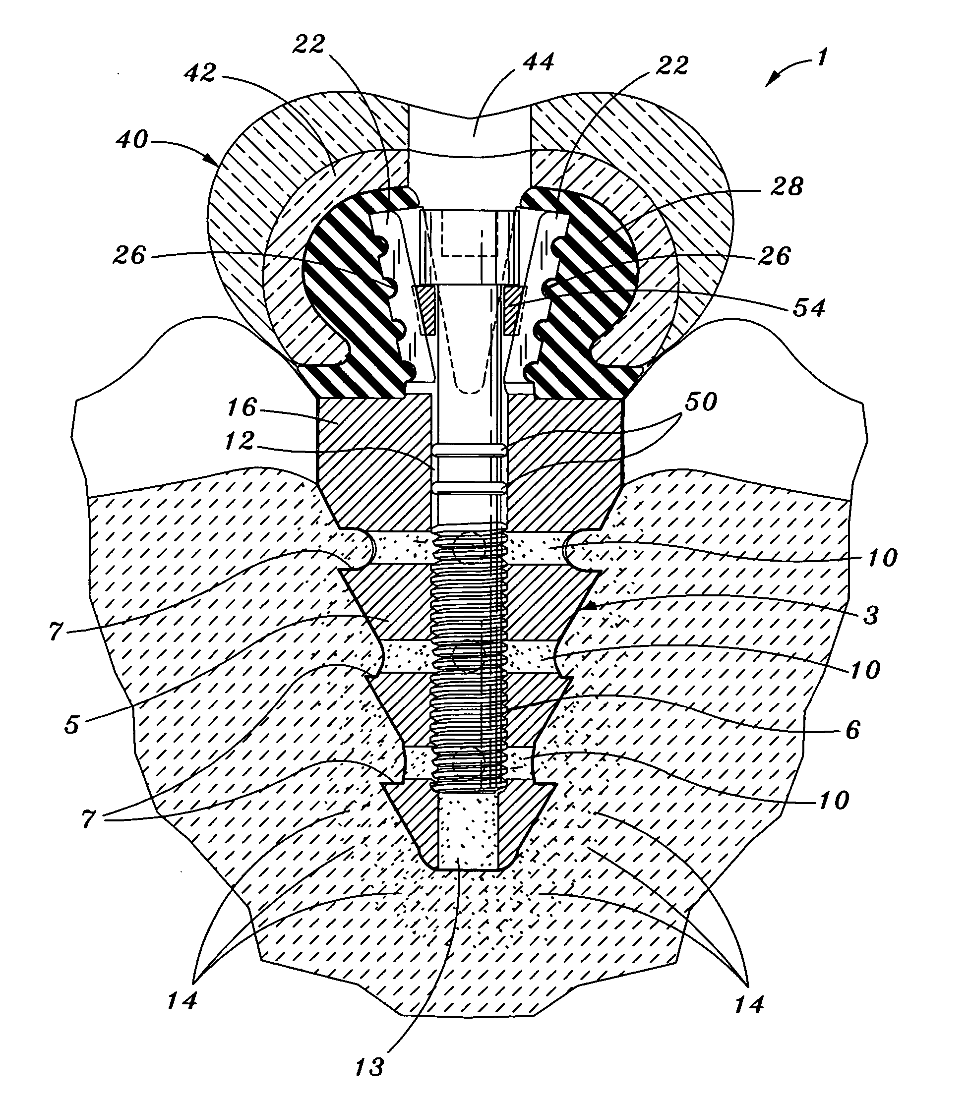
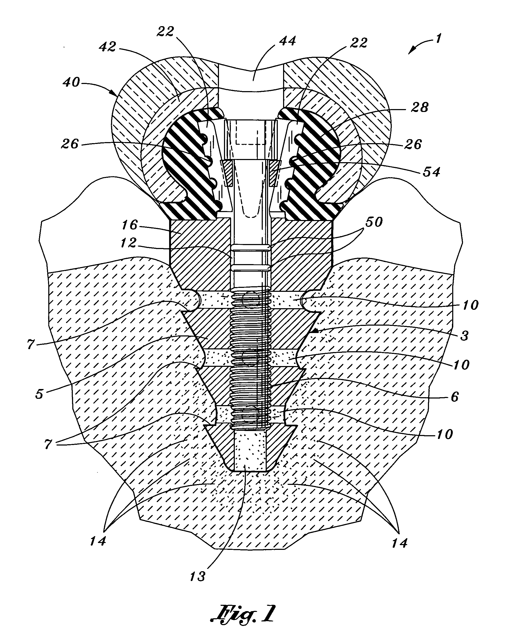
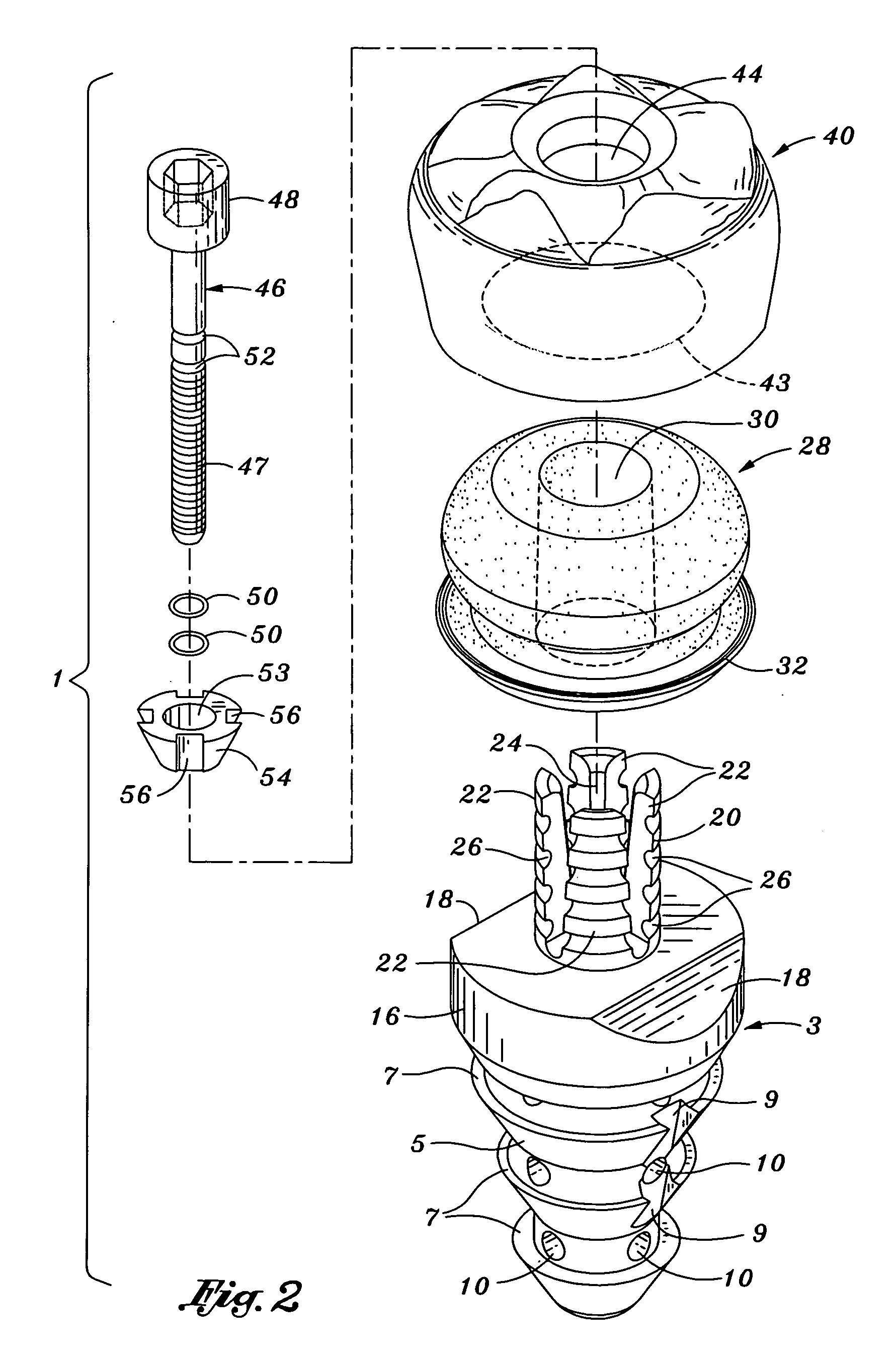
[0027] Referring initially to FIGS. 1-5 of the drawings, there is shown a biofunctional dental implant 1 which forms a first preferred embodiment of this invention. Dental implant 1 is suitable for use in the mouths of both humans and animals. The implant 1 includes a root portion 3 that is preferably manufactured from a biocompatible metallic (e.g., titanium or titanium alloy) or ceramic material that is adapted to be implanted and locked in the bone structure of a dental patient. The root portion 3 has a tapered implant casing 5 including a series of sharp edged barbs 7 extending around the exterior thereof and a set of screw threads 6 formed at the interior along a longitudinally extending channel 12. As is best shown in FIG. 1, the implant casing 5 of root portion 3 is installed within an implant socket that is made in the patient's bone structure so as to be able to support a crown portion (designated 40) above the gum line. The peripheral barbs 7 of implant casing 5 enable the...


PUM


Abstract

A biofunctional dental implant wherein a crown portion is connected to a root portion without the use of the conventional short screws, or the like. A flexible abutment projects upwardly from the root portion, and the crown portion is positioned in surrounding engagement with the flexible abutment. A threaded abutment post is advanced through the flexible abutment and into receipt by the root portion. The advancement of the abutment post through the flexible abutment generates an outward pushing force for causing a plurality of flexible splines of the abutment to bend outwardly and into engagement with an elastomeric cap of the crown portion for holding the crown portion atop the root portion. In one preferred embodiment, a replacement crown portion is detachably connected to an existing root portion by way of a removable abutment screw so as to enable a broken or worn crown portion to be removed and replaced without the need for a new surgery.

Description

BACKGROUND OF THE INVENTION [0001] 1. Field of the Invention [0002] This invention relates to a biofunctional dental implant having a crown portion connected to a root portion by means of an abutment post. The advancement of the abutment post through a flexible abutment projecting upwardly from the root portion causes the flexible abutment to apply an outward pushing force against the crown portion for holding the crown portion atop the root portion without the use of screws or similar fastening devices. [0003] 2. Background Art [0004] Natural teeth in the human mouth are supported in bone by periodontal fibers that function as shock absorbers when a compressive force is applied, such as during chewing. Through disease, accidental injury, anatomical abnormalities, age, and the like, a natural tooth may be removed or missing such that a dental appliance or prosthetic device (e.g., a crown) is implanted in the patient's bone structure to improve the patient's physical appearance and / o...

Claims


Application Information

Patent Timeline
IPC IPC(8): A61C8/00
CPCA61C8/005A61C8/0054A61C8/0057A61C8/0059A61C8/0086A61C8/0065A61C8/0066A61C8/0068A61C8/006
Inventor SAPIAN, SCHUBERT L.
Owner SAPIAN SCHUBERT L
Learn More