Method for domain name service (DNS) in a wireless ad hoc network
domain name technology, applied in the field of domain name service in a wireless ad hoc network, can solve the problems of ip address, mechanism failure to work in an ad hoc network, and inability to resolve domain names
- Summary
- Abstract
- Description
- Claims
- Application Information
AI Technical Summary
Problems solved by technology
Method used
Image
Examples
example 1
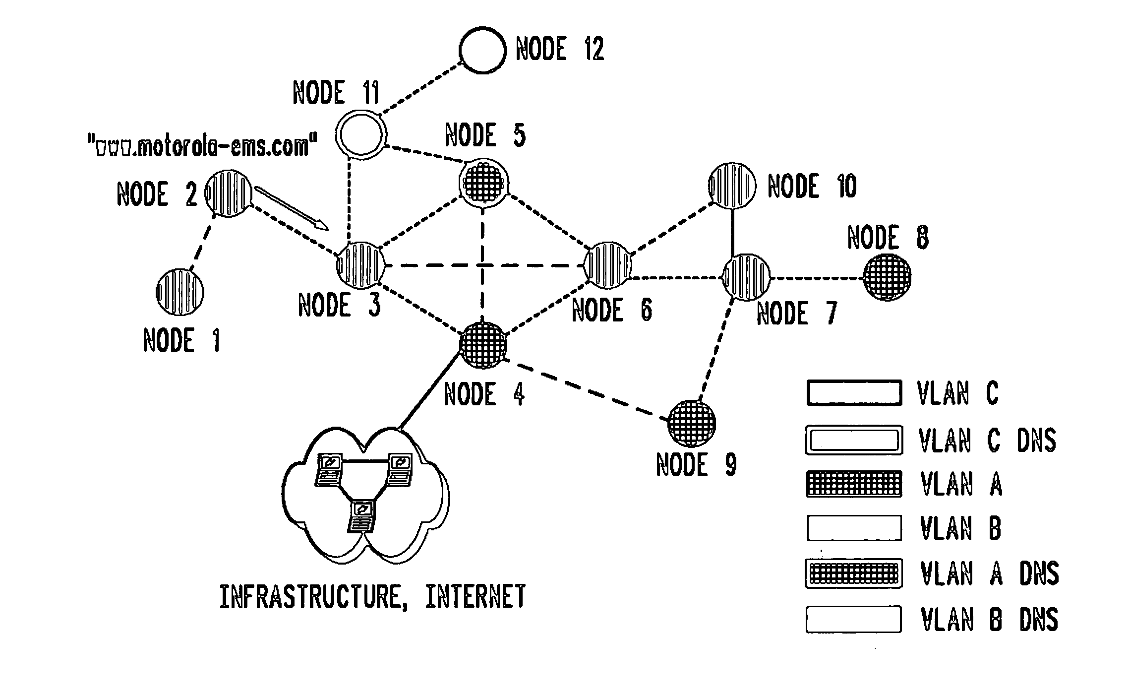
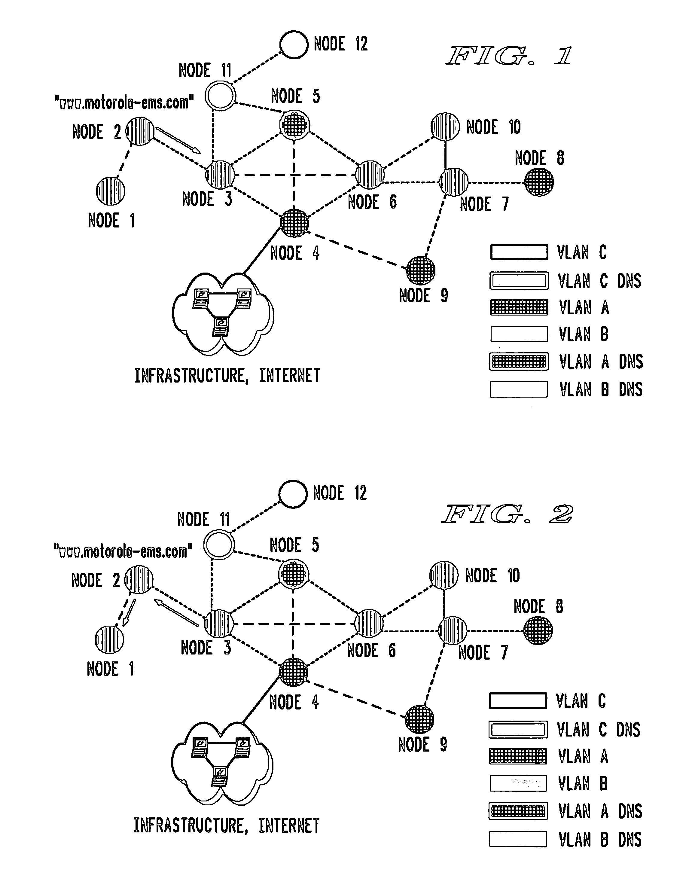
[0037]FIGS. 1-2 illustrate a first example where the DNS query is resolved within the VLAN of the requesting node. In this example, as illustrated in FIG. 1, node 1 (the requesting node belonging to VLAN B) initiates a DNS query directed towards node 3 (the primary DNS node within VLAN B) to provide an IP address for node 2 having a domain name of “www.motorola-ems.com”. Upon receipt of the DNS query, node 3 determines whether it can resolve the query based on the information stored in its internal cache. In this example, node 3 has the domain name to IP address mapping for node 2 stored in its cache and forwards the mapping to node 1 (the requesting node) as illustrated in FIG. 2. It should be noted that it is preferable that nodes 1 and 2 cache the response to the DNS query.
example 2
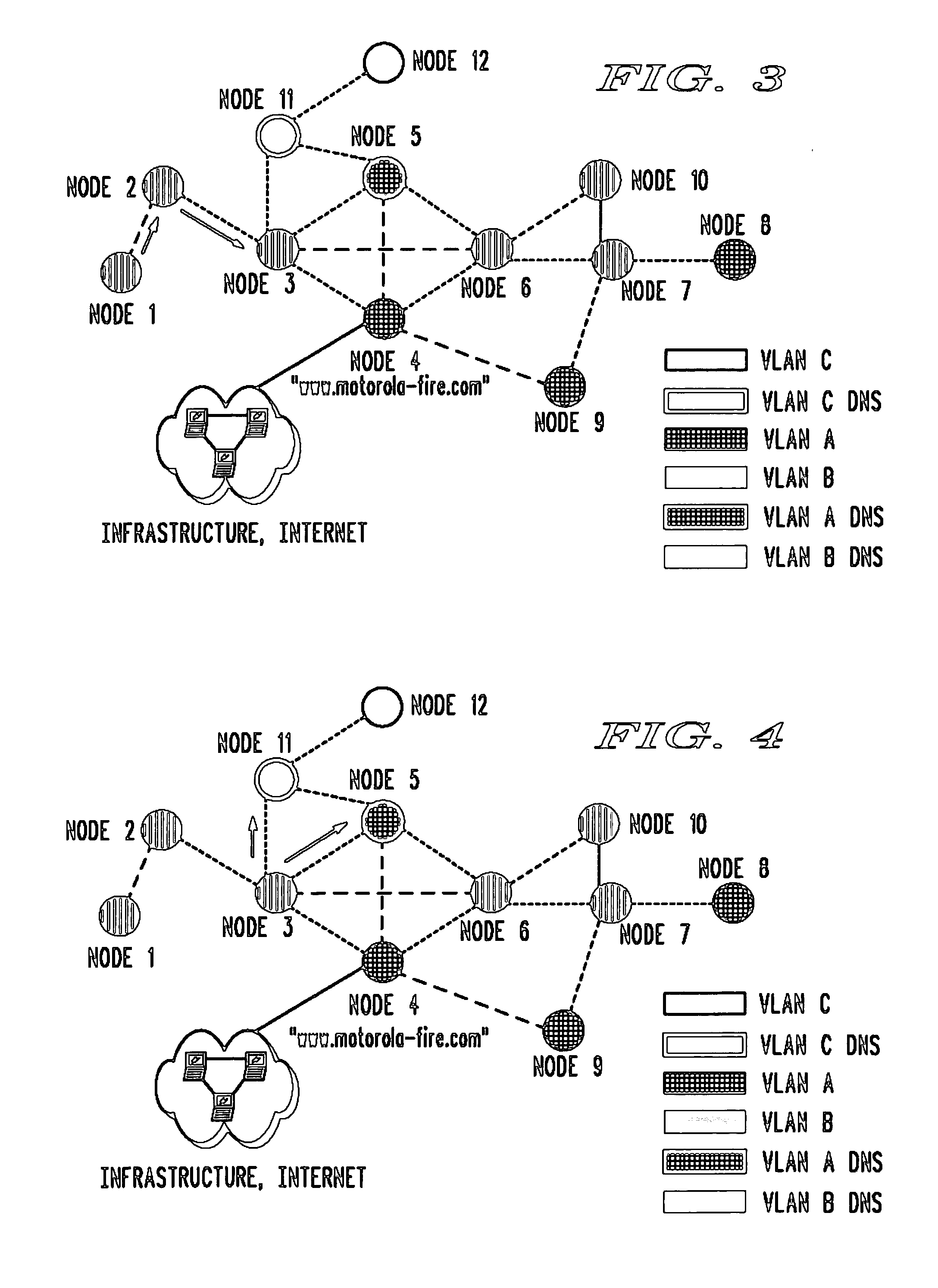
[0038] In the next example as illustrated in FIGS. 3-6, the DNS query is sent to another VLAN for domain name resolution. In this example, node 1 (the requesting node belonging to VLAN B) initiates a DNS query directed towards node 3 (the primary DNS node within VLAN B) to resolve the domain name “www.motorola-fire.com” for node 4 as illustrated in FIG. 3. Upon receipt of the DNS query, node 3 determines whether it can resolve the query based on the information stored in its internal cache. In this example, since node 3 is unable to resolve the query, it forwards the query to the other primary DNS nodes in the ad hoc network: node 5 (the primary DNS node within VLAN A) and node 11 (the primary DNS node within VLAN C) as illustrated in FIG. 4.
[0039] Upon receipt of the DNS query, node 5 determines that it is capable of resolving the query from its internal cache and sends a response to the query back to node 3 as illustrated in FIG. 5. When node 3 receives the response (the domain n...
example 3
[0040] Moving on to the third example, FIGS. 7-12 illustrate a third example of the present invention where the DNS query is sent to the infrastructure for domain name resolution automatically by another primary DNS node in the ad hoc network. As illustrated in FIG. 7, node 1 (the requesting node belonging to VLAN B) initiates a DNS query directed towards node 3 (the primary DNS node witihn VLAN B) to provide the IP address for domain name “www.motorola-police.com”. Upon receipt of the DNS query, node 3 determines whether it can resolve the query based on the information stored in its internal cache. In this example, since node 3 is unable to resolve the query, it forwards the query to the other primary DNS nodes in the ad hoc network: node 5 (the primary DNS node within VLAN A) and node 11 (the primary DNS node within VLAN C) as illustrated in FIG. 8.
[0041] In this third example, neither node 5 nor node 11 is able to resolve the DNS query for node 3. Since node 11 is unable to res...
PUM
 Abstract
Description
Claims
Application Information
 - R&D
- Intellectual Property
- Life Sciences
- Materials
- Tech Scout
- Unparalleled Data Quality
- Higher Quality Content
- 60% Fewer Hallucinations
Browse by: Latest US Patents, China's latest patents, Technical Efficacy Thesaurus, Application Domain, Technology Topic, Popular Technical Reports.
© 2025 PatSnap. All rights reserved.Legal|Privacy policy|Modern Slavery Act Transparency Statement|Sitemap|About US| Contact US: help@patsnap.com


