
Optical code reading system and method using a variable resolution imaging sensor

a reading system and variable resolution technology, applied in the field of imaging, can solve the problems of significantly affecting the performance of any imager, and the decoding time is too slow for high-performance bar code reading applications, and achieve the effect of improving performan

Inactive Publication Date: 2006-01-19
SYMBOL TECH INC
View PDF9 Cites 155 Cited by
  • Summary
  • Abstract
  • Description
  • Claims
  • Application Information

AI Technical Summary

Benefits of technology

[0010] Another aspect of the present disclosure is to provide an optical code reading system having a variable resolution imaging sensor programmed to generate a low resolution image, thereby requiring less time to transfer the image to at least one processor or decoder for decoding.
[0012] Another aspect of the present disclosure is to provide an optical code reading system with at least one variable resolution imaging sensor and incorporating all of the features and methodologies recited in the aspects identified above, thereby having improved performance, a high-speed auto-exposure system, a high-speed decode time for reading and decoding low- and high-density bar codes, an optical zoom system having no moveable parts, and other benefits and advantages.
[0015] Additionally, the present disclosure provides an optical code reading system with at least one variable resolution imaging sensor and incorporating all of the features and methodologies recited above, thereby having improved performance, a high-speed auto-exposure system, a high-speed decode time for reading and decoding low- and high-density bar codes, an optical zoom system having no moveable parts, and other benefits and advantages.

Problems solved by technology

This amount of time can substantially slow down the first-read times for an imager or imaging engine in an optical code reading system and significantly affect any imager's performance.
These decode times are too slow for high performance bar code reading applications.

Method used


Image

  • Optical code reading system and method using a variable resolution imaging sensor
  • Optical code reading system and method using a variable resolution imaging sensor
  • Optical code reading system and method using a variable resolution imaging sensor

Examples


Embodiment Construction

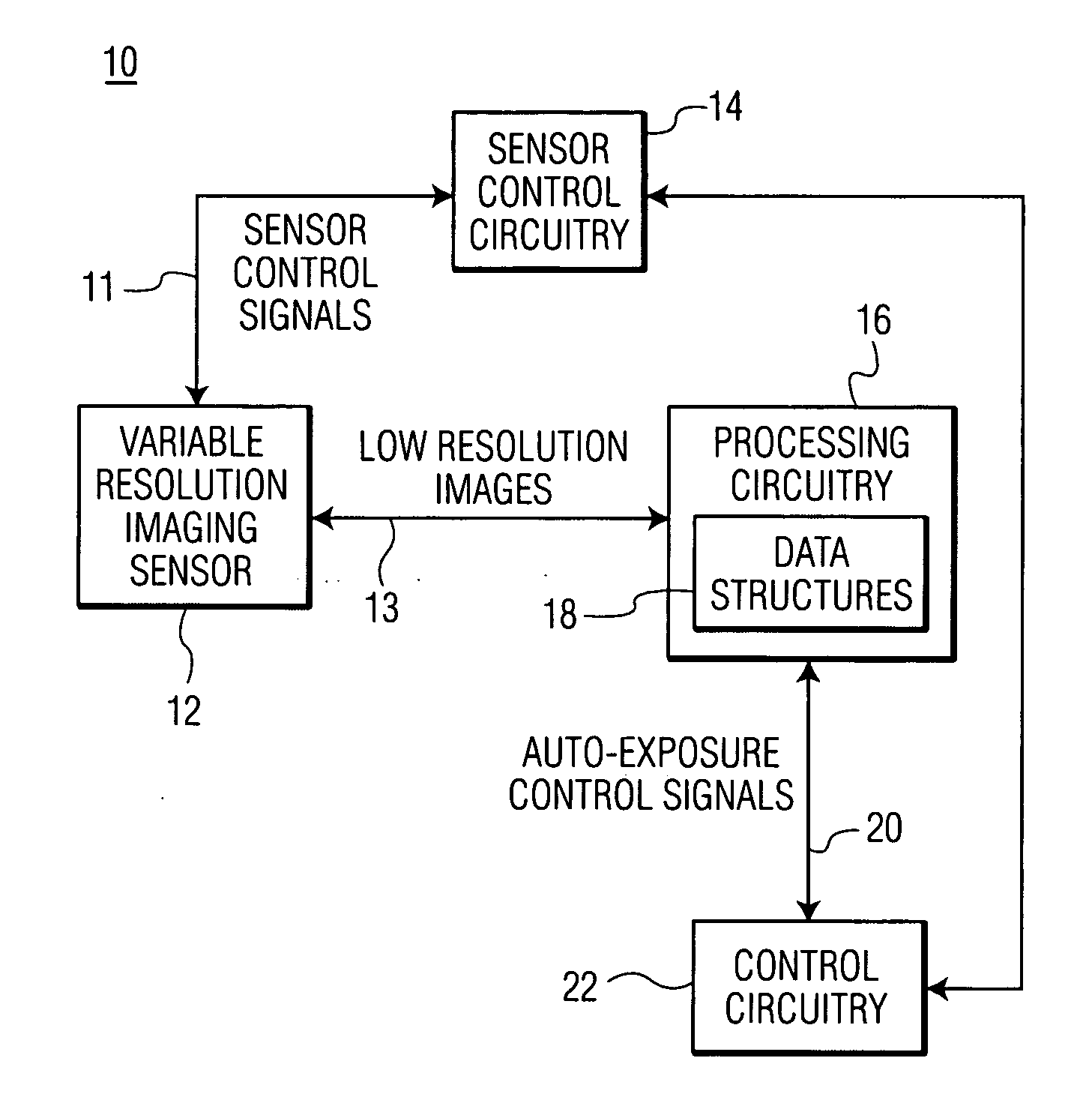
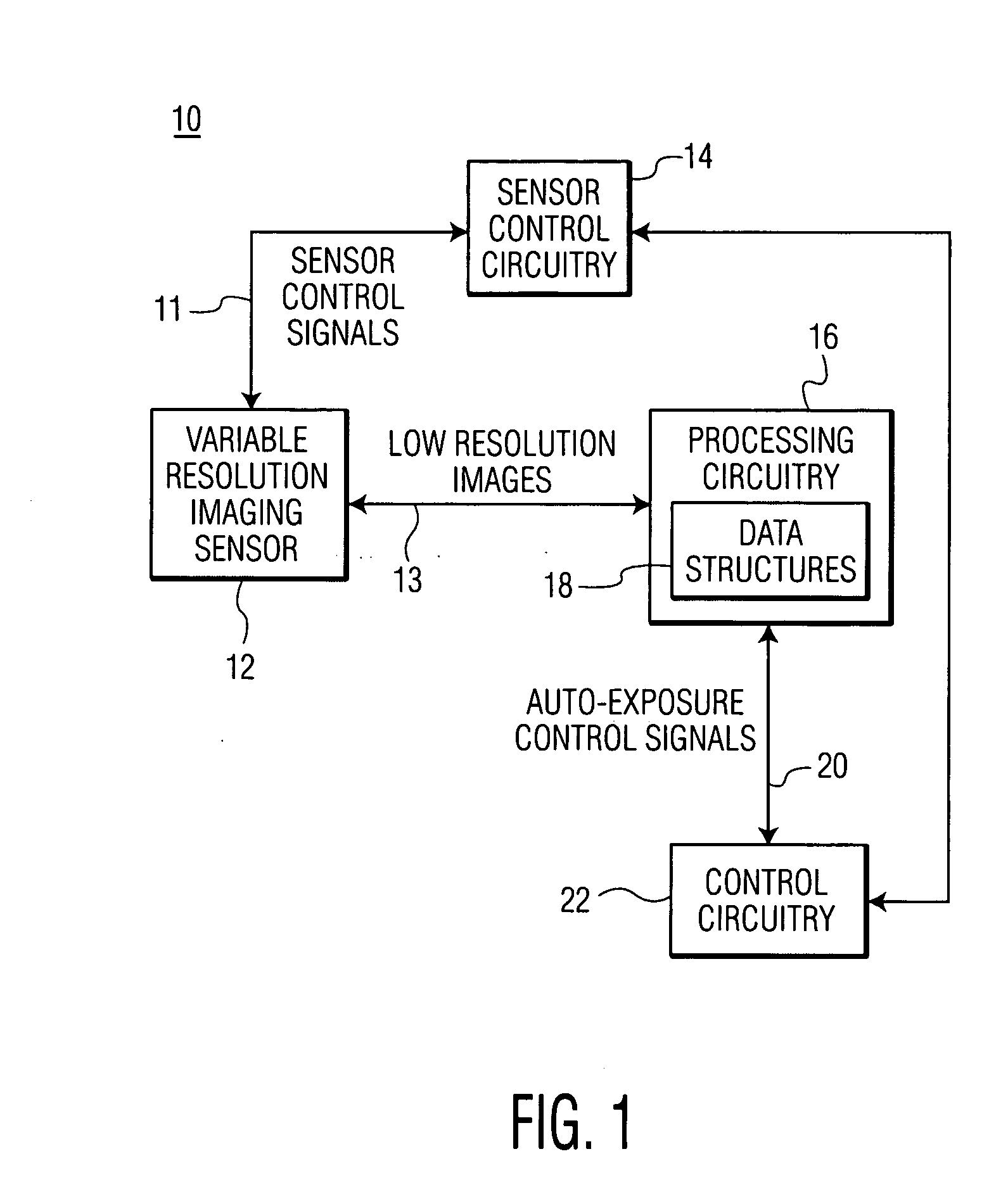
[0023] With reference to FIG. 1, there is shown a schematic illustration of an auto-exposure system for use with a variable resolution imaging sensor of an optical code reading system in accordance with the present disclosure. Even though the present disclosure is described herein with reference to an optical code reading system for imaging and decoding optical codes, such as bar codes, the aspects and features described herein can be incorporated in other systems, such as a video camera system, a digital camera system, etc.

[0024] The auto-exposure system 10 of the optical code reading system 200 (FIG. 4) makes use of a variable resolution imaging sensor 12 which is capable of generating and outputting images having at least two different resolutions, i.e., a low and a high resolution. The variable resolution imaging sensor 12 can also be capable of generating and outputting images having a plurality of resolutions ranging from low to high. The sensor 12 can be a CCD, CMOS, or othe...


PUM


Abstract

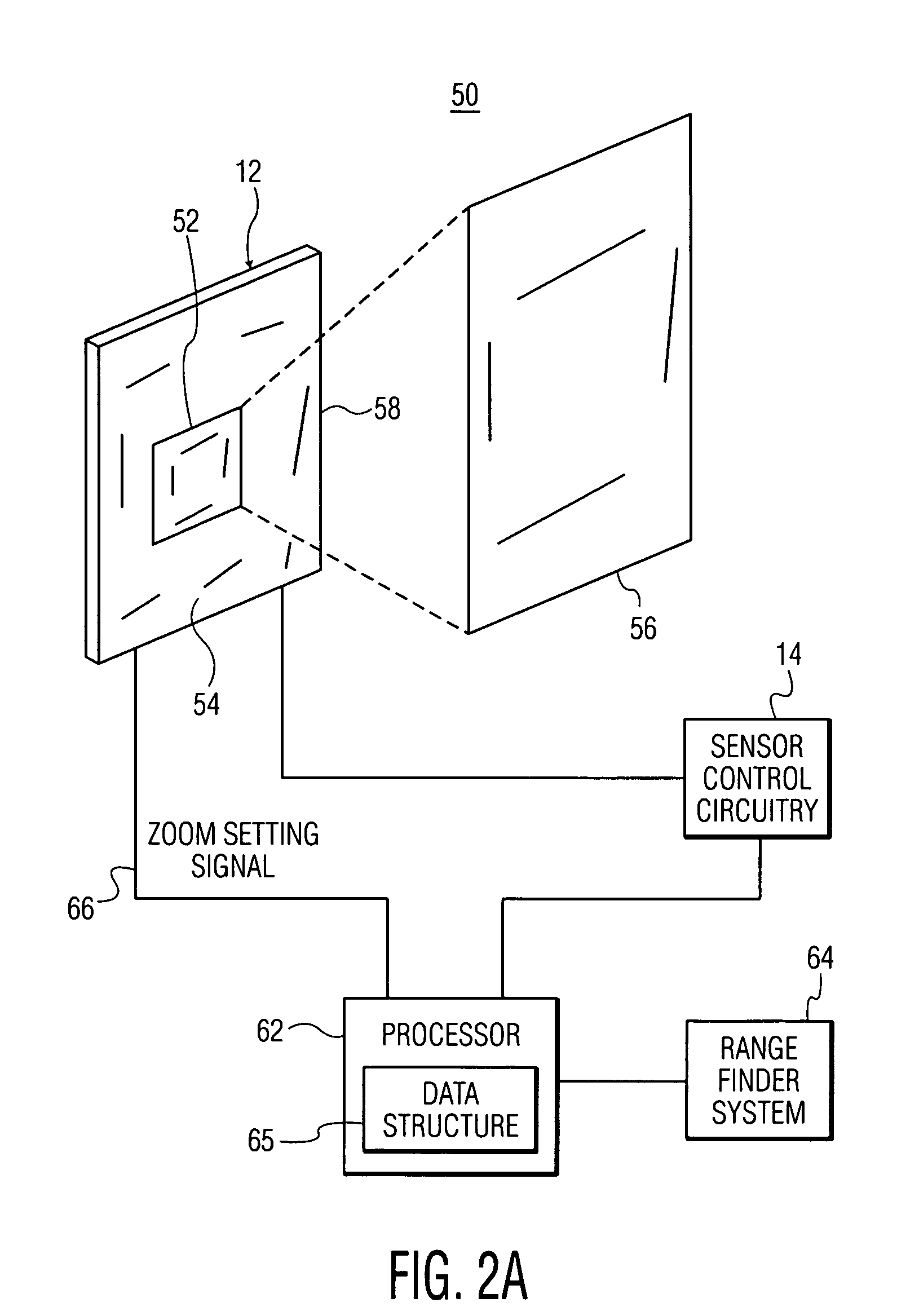
An optical code reading system having an auto-exposure system for use with a variable resolution imaging sensor in which very low resolution images are used to determine exposure parameters is presented. The very low resolution images can be transferred much faster than high resolution images which results in a very fast auto-exposure system. The optical code reading system further includes an optical zoom system for zooming in and out of a target without the use of any moveable components. The optical zoom system makes use of a binning and / or subsampling feature of the imaging sensor for zooming in and out of the target. High-speed decoding methodologies are also presented for the optical code reading system. One decoding methodology utilizes low resolution images for performing high-speed decoding. Other methodologies utilize low resolution images and higher resolution images, if the optical code imaged by the low resolution images is not decoded successfully.

Description

BACKGROUND OF THE INVENTION [0001] 1. Field of the Invention [0002] The present disclosure relates to the field of imaging, and specifically to an optical code reading system and method using a variable resolution imaging sensor. In particular, the present disclosure relates to using variable resolution imaging sensors for providing high-speed auto-exposure, high-speed decoding and 2× optical zoom in an optical code reading system. [0003] 2. Description of the Related Art [0004] CCD or CMOS imaging sensors are typically used in imaging devices, such as optical code reading devices for reading and decoding optical codes, such as bar codes. These sensors generally have an imaging pixel array having a plurality of photosensitive elements or pixels for capturing an image. Each pixel of the pixel array has a fixed aspect ratio (i.e., width-to-height). The aspect ratio of the pixels in an optical code reading device is generally determined by the type and / or density of the images, e.g., b...

Claims


Application Information

Patent Timeline
IPC IPC(8): G06K7/10G03B7/08
CPCG06K7/10722H04N5/2351H04N3/1562H04N23/71H04N25/42H04N25/443
Inventor JOSEPH, EUGENECARLSON, BRAD
Owner SYMBOL TECH INC
Learn More