
Heat exchanger of ventilating system

Inactive Publication Date: 2006-01-19
LG ELECTRONICS INC
View PDF9 Cites 2 Cited by
  • Summary
  • Abstract
  • Description
  • Claims
  • Application Information

AI Technical Summary

Benefits of technology

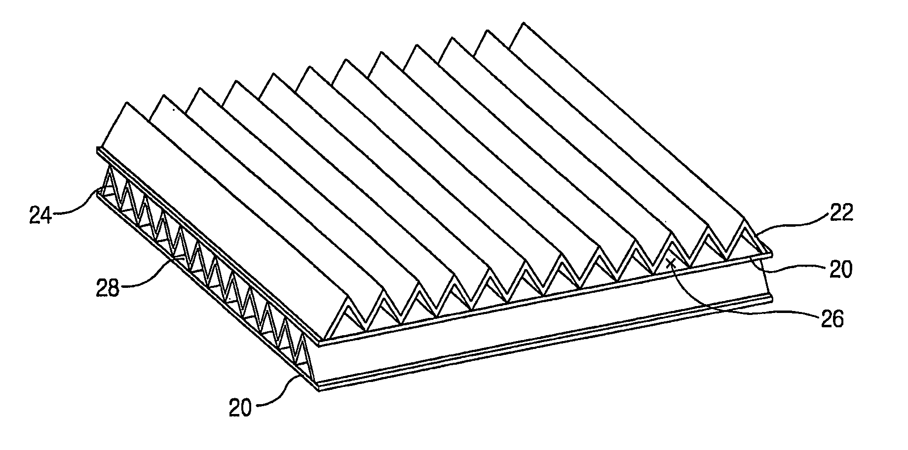
[0020] Therefore, it is an object of the present invention to provide a heat exchanger of a ventilating system that is capable of performing a latent heat exchange that outdoor air absorbs moisture contained in indoor air as well as performing a sensible heat exchange that heat contained in indoor air being discharged to outside a building is transferred to outdoor air being introduced to the interior of the building, thereby minimizing a change in an indoor temperature and humidity during a ventilating operation.

Problems solved by technology

However, the heat exchanger of a ventilating system of the conventional art has the following problem.

Method used


Image

  • Heat exchanger of ventilating system
  • Heat exchanger of ventilating system
  • Heat exchanger of ventilating system

Examples


Embodiment Construction

[0033] A heat exchanger of a ventilating system in accordance with preferred embodiments of the present invention will now be described with reference to the accompanying drawings.

[0034] There can be several embodiments of the heat exchanger of a ventilating system in accordance with the present invention, of which preferred ones will be described.

[0035]FIG. 4 is a perspective view of a heat exchanger of a ventilating system in accordance with one embodiment of the present invention.

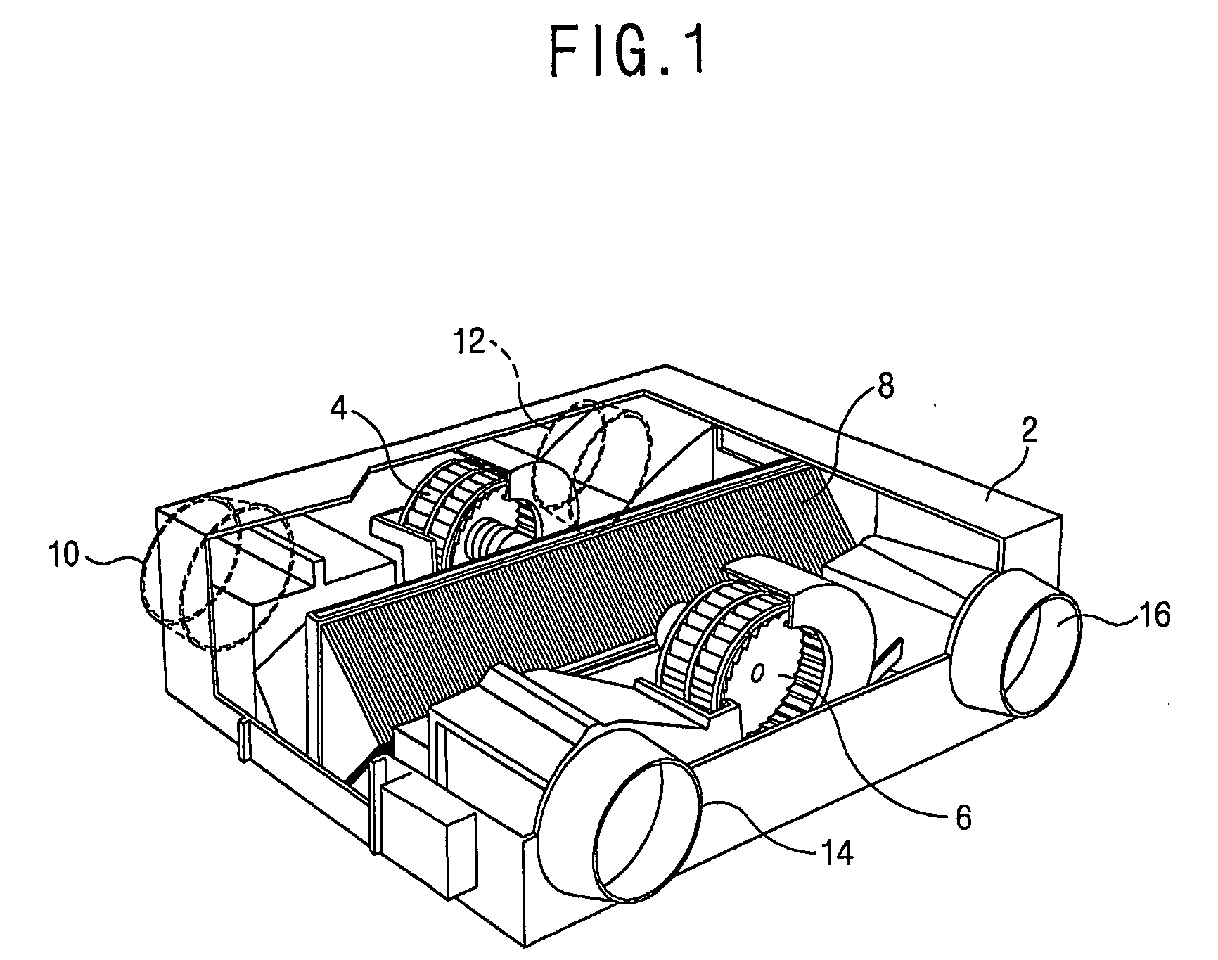
[0036] With reference back to FIG. 1, a ventilating system of the present invention includes a case 2 mounted penetratingly in a wall of a building that sections an outdoor side and an indoor side of the building. That is, one side of the case 2 is positioned at the exterior of the building while the other side of the case 2 is positioned at the interior of the building.

[0037] The outdoor suction opening 10 through which outdoor air is sucked and an outdoor discharge opening 12 through which indoor a...


PUM


Abstract

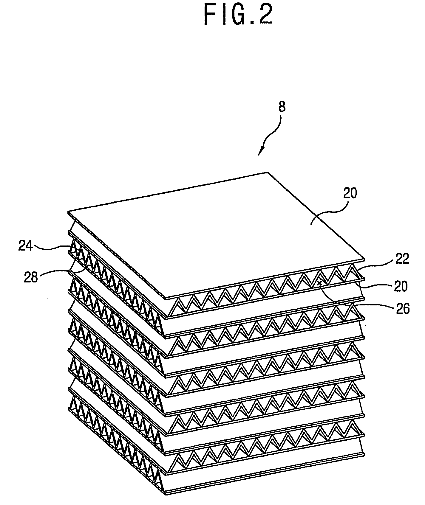
A heat exchanger of a ventilating system includes: heat exchange plates laminated with regular intervals so that a first air passage through which indoor air being discharged to outside of a building passes and a second air passage through which outdoor air being introduced into the interior of the building passes are sequentially formed; first corrugation plates attached to the first air passage and obtaining a space to allow outdoor air to pass therethrough; and second corrugation plates attached to the second air passage and obtaining a space to allow outdoor air to passtherethrough, wherein the heat exchange plates are made of a paper material with numerous fine holes that are able to generate a capillary phenomenon. A sensible heat exchange and a latent heat exchange are possible to minimize a change in a temperature and moisture.

Description

TECHNICAL FIELD [0001] The present invention relates to a heat exchanger for exchanging indoor air and outdoor air and, more particularly, to a heat exchanger of a ventilating system that is capable of exchanging sensible heat and latent heat between indoor air and outdoor air. BACKGROUND ART [0002] In general, a ventilating system is a device intended for discharging foul indoor air to outside a building and sucking outdoor fresh air into the interior of the building, which includes an air cleaner for removing dusts and foreign materials contained in indoor air and a heat exchanger for transferring heat of indoor air being discharged to outdoor air being sucked. [0003]FIG. 1 is a perspective view of a general ventilating system. [0004] As illustrated, the ventilating system includes a case 2 mounted in a wall of a building which sections an outdoor side and an indoor side; blast fans 4 and 6 inserted in the case 2 and performing a ventilating operation on air being sucked and disch...

Claims


Application Information

Patent Timeline
IPC IPC(8): F28F3/00F24F3/147F24F12/00F28D9/00F28D21/00
CPCF24F3/147F24F12/006Y02B30/563F28D9/0062F28D21/0015F24F2003/1435Y02B30/56
Inventor LEE, SEONG-HWANSHIN, SOO-YEONCHO, MIN-CHULLEE, SUNG-HWALEE, KWANG-WON
Owner LG ELECTRONICS INC
Learn More